DPS Series DPS-10 DPS-12 USER’S MANUAL Audio/Video Subwoofer System
Caution . www.velodyne.
Ta b l e o f C o n t e n t s Congratulations . . . . . . . . . . . . . . . . . . . . . . . . . . . . . . . . . . . . . . . . . . . . . . . . . . . .1 Installation . . . . . . . . . . . . . . . . . . . . . . . . . . . . . . . . . . . . . . . . . . . . . . . . . . . . . . .2 Rear Panel Connections . . . . . . . . . . . . . . . . . . . . . . . . . . . . . . . . . . . . . . . . . . . . . .6 Rear Panel Connections - Detailed Explanation . . . . . . . . . . . . . . . . . . . . . . . . . . . . . . .7 Placement . .
Congratulations Congratulations on your purchase of a Velodyne Digital Power Slot™ (DPS) subwoofer system. This system represents the state-of-the-art in low frequency reproduction. Read and follow the instructions below to insure safe and proper system operation. Warning! To prevent fire or shock hazard, do not expose this equipment to rain or moisture. To avoid electrical shock, do not open speaker enclosure or amp chassis cover. Please observe all warnings on the equipment itself.
I n s ta l l a t i o n Your new subwoofer system provides for a number of installation options. Read all the installation information below in order to determine which installation option is best for your system. Remember to perform all installation procedures with system power turned off. Figure 1. Front Panel Display Front Panel Display Figure 1 shows the front panel display, which is located on the top of your subwoofer.
The following table indicates musical style and which preset is recommended for it.
The following table shows the settings for various presets: Preset Subsonic Filter Frequency EQ Frequency EQ Level Volume Differential Movies 24 Hz 37 Hz +4 dB +8 dB R&B – Rock 27 Hz 52 Hz +3 dB +5 dB Jazz – Classical (Reference) 24 Hz N/A N/A N/A Games 34 Hz 62 +4 dB +4 dB RESTORE DEFAULTS – This feature allows you to restore default settings for your DPS subwoofer.
IMPORTANT NOTE: Some manufacturers preset their receivers with the Sub-Out channel signal at a minimum level. It is very important to verify that your receiver Sub-Out channel is set to the same output level, or higher, as your front right and left channels. Refer to your receiver manual for the individual channel level adjustment procedure.
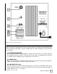
Figure 2. DPS Rear Panel Connections R e a r Pa n e l C o n n e c t i o n s Figure 2 shows the connections on the rear panel of the DPS. Following are brief descriptions of the connections described in Figure 2. More detail on these connections can be found on the next page. (1) LOW-PASS CROSSOVER Use this knob to select the high-frequency range at which you wish to cut off the signal to the subwoofer.
(B) SPEAKER LEVEL INPUT Terminals Connect these input terminals to the speaker output terminals of your amplifier or receiver. If you use this method of connection, when you go to the receiver speaker set up menu, make sure you select the large speaker option. Note: Do not use both the LINE INPUT/LFE INPUT connections and SPEAKER LEVEL INPUT connections simultaneously. (C) SPEAKER LEVEL OUTPUT Terminals Sends a speaker-level signal to the front speakers.
Speaker Level Output When connected in this fashion, your satellite speakers will be fed the same input signal as the subwoofer. This removes the lower bass from your satellites, enabling them to do a better job reproducing high frequencies and giving your receiver’s amp more headroom (up to 50% more power). You may also connect your satellites directly to your receiver or amplifier along with the subwoofer if you wish to bypass this crossover.
Placement True subwoofers operate at extremely low frequencies, which are primarily omni-directional. While it is recommended that the subwoofers be placed on the same plane as the satellite speakers, room and system conditions often dictate otherwise. Keep in mind that frequency response and output level can be drastically influenced by placement, depending on the acoustic properties of your listening room. Typically, the optimum location for a subwoofer is in a front corner of your listening room.
T roubleshooting and Service Before seeking service for your amplifier or subwoofer, please re-check all systems. Following is a simple troubleshooting guide to assist you. 1. 2. 3. 4. 5. Verify that the unit is plugged in and power outlet used is active. Is the power switch on? Is the unit receiving an input signal from your source? Have all controls (volume, crossover, phase, etc.) been properly set? If the unit has been running at high levels, one of the protection circuits may be engaged.
Specifications Specifications DPS-10 DPS-12 Driver 10” forward firing (8.2” piston diameter) 12” forward firing (9.9” piston diameter) Amplifier (Class A/B) 375 watts Dynamic/ 185 watts RMS Power 400 watts Dynamic/ 200 watts RMS power Frequency Response 28 Hz — 120 Hz (+/-3 dB) 25 Hz — 120 Hz (+/-3 dB) Low-Pass Crossover Inputs 40 Hz — 120 Hz (12 dB/octave, 24 dB ultimate) Line-level and speaker-level Outputs Speaker-level Magnet 40 oz. (2.5 lbs) 55 oz. (3.
Velodyne Products 120V DD ® Series DD-10 DD-12 DD-15 DD-18 Digital Drive 1812 Signature Edition DLS™-R Series DLS-3500R DLS-3750R DLS-4000R DLS-5000R DPS™ Series DPS-10 DPS-12 MicroVee™ ® MiniVee ® MiniVee 10 230V SPL™-R Series SPL-800R SPL-1000R SPL-1200R SPL-1500R SubContrator™ Series SC-1250 SC-8 SC-10 SC-12 SC-15 SC-IW SC-IF/IC VRP Series VRP-1000 VRP-1200 DD ® Series DD-10 DD-12 DD-15 DD-18 Digital Drive 1812 Signature Edition CHT-R Series CHT-8R CHT-10R CHT-12R CHT-15R SMS™ -1 SPL-800i SPL™-R Ser
FOR YOUR RECORDS. . . Date Puchased_________________________________________________________________ Dealer_________________________________________________________________________ Serial #________________________________________________________________________ *NOTE: Please complete and return your warranty card within ten (10) days or Register. . . ON LINE . . . It’s faster . . . and easier www.velodyne.com LIMITED WARRANTY VELODYNE ACOUSTICS, Inc.
Velodyne Acoustics, Inc. 345 Digital Drive Morgan Hill, CA 95037 408.465.2800 voice 408.779.9227 fax 408.779.9208 service fax www.velodyne.com Service E-mail: service@velodyne.com Product E-mail: help@velodyne.com Technical E-mail: techhelp@velodyne.com . 63-DPS1012 Rev B JUN07 www.velodyne.