
Operation Manual


www.velodyne.com
SC-1250 Amplier User’s Manual - 7
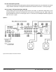
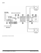
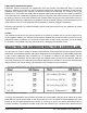
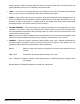
Figure 4: Balanced Line-Level Connection.
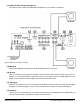
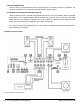
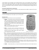
(12) Mic Input
ConnectthesuppliedmicrophonefortheAuto-EQfeaturetothismini-jack.
(13) IR Input
Thisisaconnectionthatallowstheutilizationofathirdpartyinfraredremotesensor,suchasElanor
Xantech, or an extended cable for placement closer to your other remote controlled equipment. This
keeps you from awkward control angles using the infrared remote control.
(14) 12V Trigger
Whenthis2-conductorminijackisconnected,theamplierremainsinpower-omodeuntilthetrigger
isapplied.Thecorrecttriggeris+12Vonthetipoftheconnectorrelativetothegroundedsleeve.
(15) RS-232 In
Use this port to communicate with a touch panel remote control. See Appendix A for anexplanation of
the use of the serial port, available commands, and their formats.
(11) Balanced XLR LFE Input (See Figure 4)
ThisXLRinputjackreceivesthebalancedLFEsignalfromyourreceiverorprocessor.