SC-602 Amplifier SubContractor™ Series USER’S MANUAL S C - 6 0 2 A m p l i f i e r, S C - 6 0 0 I W, SC-600 IF/IC Subwoofers
C a u t i o nI !M P O R T A N T SAFETY INSTRUCTIONS Caution To reduce the risk of electric shock, do not remove cover (or back). No user-serviceable parts inside. Refer servicing to qualified service personnel. The lightning flash with arrowhead symbol is intended to alert the user to the presence of uninsulated “dangerous voltage” within the product’s enclosure that may be of sufficient magnitude to constitute a risk of electric shock to persons.
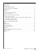
Ta b l e o f C o n t e n t s Congratulations . . . . . . . . . . . . . . . . . . . . . . . . . . . . . . . . . . . . . . . . . . . . . . . . . . . .1 Product Features . . . . . . . . . . . . . . . . . . . . . . . . . . . . . . . . . . . . . . . . . . . . . . . . . . .1 – SC-602 Subwoofer Amplifier . . . . . . . . . . . . . . . . . . . . . . . . . . . . . . . . . . . . . . . . .1 – SC-600 IW, SC-600 IF/IC Subwoofers . . . . . . . . . . . . . . . . . . . . . . . . . . . . . . . . . .2 Setup Checklist . . . .
Congratulations Congratulations on your purchase of a Velodyne SubContractor Series (SC) 602 amplifier and associated subwoofer. This system represents the state-of-the-art in low frequency reproduction. Read and follow the instructions below to ensure safe and proper system operation. Warning! To prevent fire or shock hazard, do not expose this equipment to rain or moisture. To avoid electrical shock, do not open the speaker enclosure or the amp chassis cover.
S C - 6 0 0 I W, S C - 6 0 0 I F / I C S U B W O O F E R S SC-600 IW (In-Wall): - Two high excursion 6.5” active drivers, two 12.5” x 3” oval passive radiators with ribbed rubber surround - High-excursion rubber surround - 2” dual layer voice coil - Frequency Response: 37 - 120 Hz (+/- 3 dB) - 4 ohm impedance SC-600 IF/IC (In-Floor/In-Ceiling): - 12” (9.7” piston diameter) subwoofer - 2.
I n s ta l l a t i o n F R O N T P A N E L C O N T R O L S A N D D I S P L AY S F R O N T P A N E L C O N T R O L S A N D D I S P L AY S 602 Figure 1: Front Panel Connections of the SC-602 amplifier. Following are brief descriptions of the controls described in Figure 1. More detail on these controls can be found in the next section. (1) Power Switch This button forces your SC-602 amplifier into standby mode. The power LED turns amber, the numeric LED shuts off, and the amplifier puts out no power.
(6) LED Numeric Indicator This LED supplies information on volume, crossover, woofer type, and other information. The light button on the remote deactivates this display. Upon startup, the display shows the model of subwoofer the SC-602 amp is set to, then reverts to the volume indicator. (7) Volume Control These buttons allow you to balance the output from the subwoofer with the output of the main speakers in your system.
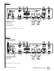
Option 1 14 13 ALWAYS ON 15 19 20 STANDBY MODE FUSE LOCATION - 115V - - 9 10 11 12 16 17 18 SC-600 Subwoofer SC-600 Subwoofer 21 22 19 20 Line-Level Subwoofer Signal from Source (LFE) Note: A “Y” connector can be used as an option. Figure 2A: Mono (LFE) Line-Level Connection. Option 2 Stereo Line-Level Output to Another System, e.g.
(11) IR Input An IR repeater can be connected to this mini-jack. (12) 12V Trigger When this mini-jack is connected, the unit remains in power-off mode until 12 volts is supplied across the two leads. Polarity is irrelevant. (13) RS-232 In Use this port to communicate with an RS-232 controlled touch panel system. See Appendix A for an explanation of the use of the serial port, available commands and their formats.
A/V RECEIVER SPEAKER R L Speaker-Level Signal from Source 13 14 ALWAYS ON 15 19 20 STANDBY MODE FUSE LOCATION - 115V - - 9 10 11 12 16 R 17 18 SC-600 Subwoofer SC-600 Subwoofer 21 22 L 80 Hz and Above to Satellite Speakers Figure 3: Speaker-Level Connection. (17) and (18) Subwoofer Line Level (LFE) Connection Terminals Connect the output terminals to the subwoofer being controlled by the SC-602 amplifier.
(21) Fuse If the unit is not functioning, check the fuse. If the fuse is blown, replace with an identically rated fuse. If the fuse blows again, refer the unit for service. (22) 115V or 230V Operation Selectable Switch This selectable voltage switch is factory preset for the correct voltage in the geographical region in which the product is sold.
R e a r Pa n e l C o n n e c t i o n s — D e ta i l e d E x p l a n a t i o n The SC-602 amplifier is equipped with both speaker-level and line-level inputs. Use the RCA/Phono type “INPUT” jacks when connecting from a pre-amp, signal processor, or line-level crossover. The “SPEAKER LEVEL INPUT” jacks connect directly to the speaker outputs of an integrated amplifier or receiver. Your amplifier section will notice no additional loading effects when you use these inputs because of their high impedance.
In these installations, you may want to bypass the crossover in either the processor or the Velodyne SC-602 amplifier as described above. However, in some cases you may want to use BOTH crossovers. If you choose to do this you should stagger the frequencies, (i.e., 120 Hz subwoofer, 80 Hz processor) for best results. Note: If not using an external crossover, you should use the built-in crossover for optimal performance.
Selecting the Subwoofer to be Controlled Your SC-602 amplifier can control the Velodyne SC-600 Series subwoofers as well as generic passive subwoofers. Special internal software settings are designed to maximize performance and reliability depending on the model of subwoofer being controlled, so it is important to match the SC-602 amplifier with the subwoofer it is controlling. The SC-602 amplifier comes with a default setting for the SC-600 IW subwoofer.
Usage This section addresses day-to-day usage of your SC-602 amplifier. Remote Control The features of the SC-602 remote control are listed below. • POWER — This button forces your SC-602 amplifier unit into standby mode. The power LED turns amber, the numeric LED shuts off, and the amplifier puts out no power. The unit will remain in this mode until the POWER button is pressed again. To fully deactivate (i.e. power down) the unit, use the main power switch on the back panel.
• VOLUME CONTROL — This control allows you to balance the output from the subwoofer with the output of the main speakers in your system. This control should be set to achieve similar volume level of both the main speakers and subwoofer. When pressing volume up or down, the volume level is shown on the numeric LED on the front panel. WARNING: Some manufacturers preset their receivers with the Sub-Out channel signal at a minimum level.
The following table indicates musical style and which preset is recommended for it. MUSICAL STYLE Action Adventure Movies Country – Rock Country – Soft Folk Indie Music Pop Rock Alternative Rock Blues Broadway and Vocalists Children’s Music Christian and Gospel Classic Rock Classical Dance and DJ Hard Rock/Heavy Metal Latin Music Miscellaneous Movies – Non-Action Adventure New Age Opera and Vocal R&B Rap and Hip-Hop Soundtracks Video Games . www.velodyne.
R e s t o r i n g D e fa u l t s There is a feature that allows you to restore default settings for your SC-602 amplifier. By pressing presets in EXACTLY the following order on the remote, the unit’s power light will blink indicating that you have restored defaults.
T roubleshooting and Service Before seeking service for your amplifier or subwoofer, please re-check all systems. Following is a simple troubleshooting guide to assist you. 1. 2. 3. 4. 5. Verify that the unit is plugged in and power outlet used is active. Is the power switch on? Is the unit receiving an input signal from your receiver or processor? Have all controls on the amplifier (volume, crossover, phase, etc.
Specifications www.velodyne.
Appendix A: RS-232 Serial Overview and Commands Introduction This document outlines Velodyne’s SubContractor (SC) RS-232 protocol specification. This protocol indicates how SC products receive run-time commands from devices such as Creston® Universal Remote Controls.
RS-232 Commands .
Velodyne Products 115 - 120V DD ® Series DD-10 DD-12 DD-15 DD-18 Digital Drive 1812 Signature Edition DEQ-R Series DEQ-8R DEQ-10R DEQ-12R DEQ-15R DLS™-R Series DLS -3500R DLS -3750R DLS -4000R DLS -5000R Impact Series Impact - Mini Impact -10 Impact -12 220 - 240V MiniVee® ® MiniVee 10 Optimum Series Optimum-8 Optimum-10 Optimum-12 SMS™-1 SubContractor™ Series SC-1250 SC-10 SC-12 SC-15 SC-IW SC-IF/IC SC-600 Amp SC-602 Amp SC-600 IW SC-600 IF/IC DD ® Series DD-10 DD-12 DD-15 DD-18 Digital Drive 1812 Sign
FOR YOUR RECORDS. . . Date Purchased_________________________________________________________________ Dealer_________________________________________________________________________ Serial #________________________________________________________________________ *NOTE: Please complete and return your warranty card within ten (10) days or Register. . . ON LINE . . . It’s faster . . . and easier www.velodyne.com LIMITED WARRANTY - U.S. AND CANADA ONLY VELODYNE ACOUSTICS, Inc.
Velodyne Acoustics, Inc. 345 Digital Drive Morgan Hill, CA 95037 408.465.2800 voice 408.779.9227 fax 408.779.9208 service fax www.velodyne.com Service E-mail: service@velodyne.com Product E-mail: help@velodyne.com Technical E-mail: techhelp@velodyne.com . 63-SC602 RevA SEP 2009 www.velodyne.