INSTALLER MANUAL VB0175 VB0176 HRV CONSTRUCTO 1.5ES* HRV SOLO 1.5ES* (PART NOS 46110 AND 1601702) (PART NOS 46720 AND 46725) HRV CONSTRUCTO 2.0ES* HRV SOLO 2.0ES* (PART NO. 47110) (PART NO. 47720) * THESE PRODUCTS EARNED THE ENERGY STAR® BY MEETING STRICT ENERGY EFFICIENCY GUIDELINES SET BY NATURAL RESOURCES CANADA AND THE US EPA. THEY MEET ENERGY STAR REQUIREMENTS ONLY WHEN USED IN CANADA. ERV CONSTRUCTO 2.0ES (PART NO.
ABOUT THIS MANUAL Because of the large amount of models covered by this publication, the illustrations are typical ones. Some details of your unit may be slightly different than the ones shown. Please take note that this manual uses the following symbols to emphasize particular information: ! WARNING Identifies an instruction which, if not followed, might cause serious personal injuries including possibility of death.
TABLE OF CONTENTS 1. TECHNICAL DATA ..................................................................................................................................... 4-5 1.1 1.2 1.3 1.4 AIR DISTRIBUTION (NORMAL OPERATION) ............................................................................................................................ 4 AIR DISTRIBUTION (DEFROST MODE) ..............................................................................................................................
1. TECHNICAL DATA 1.1 AIR DISTRIBUTION (NORMAL OPERATION) 1.2 AIR DISTRIBUTION (DEFROST MODE) VF0053 VF0052 1.3 DEFROST CYCLES TABLES HRV CONSTRUCTO 1.5ES AND SOLO 1.5ES UNITS OUTSIDE TEMPERATURE DEFROST CYCLES (MINUTES) CELCIUS (°C) FAHRENHEIT (°F) DEFROSTING -5 23 7 OPERATION TIME BETWEEN EACH DEFROST CYCLES 50 EXTENDED DEFROST CYCLES DEFROSTING OPERATION TIME BETWEEN EACH DEFROST CYCLES 10 30 -15 5 7 25 10 20 -27 -17 10 20 10 15 ERV CONSTRUCTO 2.
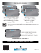
1. TECHNICAL DATA (CONT’D) 1.4 DIMENSIONS 1.4.1 HRV CONSTRUCTO 1.5ES, HRV CONSTRUCTO 2.0ES, HRV SOLO 1.5ES AND HRV SOLO 2.0ES 35” (891 mm) Hooks Location for Hanging Chains 17¼” (438 mm) 30¼” (768 mm) Motorized Damper Terminal Block Location 17” (432 mm) Heat Recovery Core Door Power Cord 36” (914 mm) VK0077A 6” (152 mm) Blower Assembly 1.4.2 ERV CONSTRUCTO 2.
2. TYPICAL INSTALLATIONS NOTE: Installation may vary according to the model number and the position; normal or reverse (Solo units only) in wich the unit is installed. There are three common installation methods. 2.1 FULLY DUCTED SYSTEM (Primarily for homes with radiant hot water or electric baseboard heating. See illustration at right.) Moist, stale air is exhausted from the high humidity areas in the home, such as bathrooms, kitchen and laundry room.
3. INSTALLATION ! WARNING When applicable local regulation comprises more restrictive installation and/or certification requirements, the aforementioned requirements prevail on those of this document and the installer agrees to conform to these at his own expenses. ! WARNING When performing installation, servicing or cleaning the unit, it is recommended to wear safety glasses and gloves. 3.1 INSPECT THE CONTENT OF THE BOX • Inspect the exterior of the unit for shipping damage.
3. INSTALLATION (CONT’D) 3.4 CALCULATING THE DUCT SIZE Use the table below to ensure that the ducts you intend to install will be carrying air flows at or under the recommended values. Avoid installing ducts that will have to carry air flows near the maximum values and never install a duct if its air flow exceeds the maximum value.
3. INSTALLATION (CONT’D) 3.5 INSTALLING THE DUCTWORK AND THE REGISTERS ! WARNING Never install a stale air exhaust register in a room where there is a combustion device, such as a gas furnace, a gas water heater or a fireplace. CAUTION The ductwork is intended to be installed in compliance with all local and national codes that are applicable. 3.5.1 FULLY DUCTED SYSTEM (AS ILLUSTRATED IN SECTION 2.
3. INSTALLATION (CONT’D) 3.5 INSTALLING THE DUCTWORK AND THE REGISTERS (CONT’D) 3.5.3 SIMPLIFIED INSTALLATION (AS ILLUSTRATED IN SECTION 2.3) ! WARNING When performing duct connection to the furnace, installation must be done in accordance with all applicable codes and standards. Please refer to your local building code. CAUTION When performing duct connection to the furnace ducts (Method 1), these ducts must be sized to support the additional airflow produced by the ERV/HRV.
3. INSTALLATION (CONT’D) 3.6 CONNECTING THE DUCTS TO THE UNIT CAUTION If ducts have to go through an unconditioned space (e.g.: attic), always use insulated ducts. INSULATED FLEXIBLE DUCTS Use the following procedure for connecting the insulated flexible duct to the ports on the unit (exhaust to outside and fresh air from outside). Pull back the insulation to expose the flexible duct and place it over inner port ring.
3. INSTALLATION (CONT’D) 3.7 INSTALLING THE EXTERIOR HOODS Choose an appropriate location for installing the exterior hoods: 6” ø (152 MM) EXHAUST HOOD • At a minimum distance of 6 feet (1.8 m) between the hoods to avoid cross-contamination INTAKE HOOD • At a minimum distance of 18 inches (457 mm) from the ground 18” (457 MM) 6’ (1.8 M) ! WARNING Make sure the intake hood is at least 6 feet (1.
3. INSTALLATION (CONT’D) 3.8 CONNECTING THE DRAIN (CONT’D) 3.8.2 ERV UNIT 8" MIN. 8" MAX. VD0287 ± 1" Insert a drain plug (included in parts bag) in alternate drain fitting located on top of the unit. VO0243A Make a water trap loop in the tube to prevent the unit from drawing unpleasant odors from the drain source. Run the tube to the floor drain or to an alternative drain pipe or pail.
4. CONTROLS (CONT’D) 4.2 ELECTRICAL CONNECTION TO OPTIONAL WALL CONTROL For more convenience, this unit can also be controlled using an optional main wall control. ! WARNING Always disconnect the unit before making any connections. Failure in disconnecting power could result in electrical shock or damage of the wall control or electronic module inside the unit. CAUTION Never install more than one optional main wall control per unit.
4. CONTROLS (CONT’D) 4.2 ELECTRICAL CONNECTION TO OPTIONAL WALL CONTROL (CONT’D) 4.2.3 ELECTRICAL CONNECTION TO LITE-TOUCH CONSTRUCTO (ALL UNITS) OR SIMPLE-TOUCH CONSTRUCTO MAIN WALL CONTROL (EXCLUSIVELY FOR SOLO UNITS) 4.2.
nc BN 16 VE0257A Fan motor M1 R BL GND GN HI O COM GY LO MED BN nc Motor BK capacitor C1 BK nc nc GY BN BN nc 12 GN BK O W nc nc nc BK R BK W Critical characteristic.
7. BALANCING THE UNIT 7.1 WHAT YOU NEED TO BALANCE THE UNIT • A magnehelic gauge capable of measuring 0 to 0.5 inch of water (0 to 125 Pa) and 2 plastic tubes. • The balancing chart of the unit. VP0009 7.2 PRELIMINARY STAGE TO BALANCE THE UNIT • Seal all the unit ductwork with tape. Close all windows and doors. • Turn off all exhaust devices such as range hood, dryer and bathroom fans. • Make sure the integrated balancing dampers are fully open.
8. SERVICE PARTS 1 19 2 18 3 5 4 15 17 14 8 6 7 15 9 16 12 10 13 11 VL0050 ITEM 1 2 3 4 5 6 7 8 9 10 11 12 13 14 15 16 17 18 19 * * DESCRIPTION Hinge assembly kit Damper supply port assembly Damper system actuator (including no. 4) Thermistor kit Capacitor 7.5 μF Electronic board Transformer Double collar port Blower assembly (including no.
9. TROUBLESHOOTING If the integrated control LED of the unit is flashing, this means the unit sensors detected a problem. See the list below to know where on the unit the problem occurs. LED flashes GREEN (double blink). LED flashes AMBER. • Thermistor error. • Damper error. Replace the thermistor kit. Go to point 10. ! WARNING A few diagnosis procedures may require the unit to be in operation while proceeding. Open the unit door and bypass its magnetic switch by putting the door white magnet on it.
9. TROUBLESHOOTING (CONT’D) PROBLEMS POSSIBLE CAUSES YOU SHOULD TRY THIS 7. The wall control does • The wires may be in reverse position. • Ensure that the color coded wires have been connected to their appropriate not work OR its indicator places. flashes. • Inspect every wire and replace any that are damaged. • The wires may be broken. • The wire in the wall OR the wall • Remove the wall control and test it right beside the unit using another shorter wire.