
Technical data


10
3. INSTALLATION (CONT’D)
3.5 INSTALLING THE DUCTWORK AND THE REGISTERS (CONT’D)
When performing duct connection to the furnace ducts (Method 1), these ducts must be sized to support the
additional airflow produced by the ERV/HRV. Also, the supply duct must be a metal duct. It is recommended that
the ERV/HRV is running when the furnace is in operation in order to prevent backdrafting inside ERV/HRV.
3.5.3 SIMPLIFIED INSTALLATION (AS ILLUSTRATED IN SECTION 2.3)
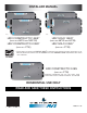
There are two methods (illustrated below) for connecting the unit to the furnace ducts:
M
ETHOD 1: RETURN-SUPPLY METHOD 2: RETURN-RETURN
When performing duct connection to the furnace, installation must be done in accordance with all applicable
codes and standards. Please refer to your local building code.
If using Method 2, make sure the furnace blower operation is synchronized with the unit operation! See Section 5.
MINIMUM
3’ (0.9 M)
STALE AIR INTAKE:
• Cut an opening into the furnace return duct not less than 10 feet (3.1 m) from the furnace.
• Connect this opening to the stale air intake port of the HRV/ERV (as shown above).
FRESH AIR DISTRIBUTION:
Same instructions as for Method 1 or Method 2, section 3.5.2 in previous page)
A+B= NOT LESS
THAN 10’ (3.1 M)
B
A
VJ0086
METAL DUCT
MINIMUM
18’’ (0.5 M)
A+B= NOT LESS
THAN 10’ (3.1 M)
B
A
VJ0087
For Method 2 (Return-Return), make sure there is a distance of at least 3 feet (0.9 m) between the 2 connections to the furnace
duct.
NOTE: For Method 1, it is not essential to synchronize the furnace blower operation with the HRV/ERV operation, but we
recommend it.
CAUTION
CAUTION
WARNING
!