
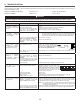
Technical data


13
4. CONTROLS
4.1 INTEGRATED CONTROL
All units are equipped with an integrated control, located in front of the electrical compartment. Use the
push button (1) to control the unit. The LED (2) will then show on which mode the unit is in.
NOTES: 1. The integrated control must be turned OFF to use an optional main control.
2. If an optional auxiliary control is used, if activated, this auxiliary control will override the
optional main control.
If a problem occurs during the unit operation, its integrated control LED (2) will blink. The color of the blinking light depends on the
type of error detected. Refer to Section 9 Troubleshooting on pages 19 and 20 for further details.
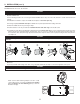
4.1.1 BOOT SEQUENCE
The unit boot sequence is similar to a personnal computer boot sequence. Each time the unit is plugged after being unplugged, or
after a power failure, the unit will perform a 30-second booting sequence before starting to operate. During the booting sequence,
the integrated control LED will light GREEN (unit set in normal defrost) or AMBER (unit set in extended defrost) for 5 seconds, and
then will shut off for 2 seconds. After that, the LED will light RED for the rest of the booting sequence. During this RED light phase,
the unit is checking and resetting the motorized damper position. Once the motorized damper position completely set, the RED
light turns off and the booting sequence is done.
NOTE: No command will be taken until the unit is fully booted.
4.1.2 SETTING EXTENDED DEFROST
The unit is factory set to normal defrost. In cold region, it may be necessary to setup extended defrost. During
the first 5 seconds of booting sequence, while the integrated control LED is GREEN, press on push button until
the LED turns AMBER (about 3 seconds).
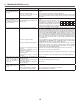
Refer to table below to see how to operate the unit using its integrated control.
PRESS ON PUSH BUTTON LED COLOR RESULTS
ONCE AMBER UNIT IS ON LOW SPEED
TWICE GREEN UNIT IS ON HIGH SPEED
THREE TIMES NO LIGHT UNIT IS OFF
VD0278
1
2
VD0281
For Solo units only, when installed in reverse postion (upside down) in a cold region where outside temperature
could drop below -20C (-4F) for more than 5 days in a row, the unit must always be set in extended defrost.
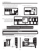
3.8.2 ERV UNIT
Make a water trap loop in the tube to prevent the unit from drawing unpleasant odors from
the drain source. Run the tube to the floor drain or to an alternative drain pipe or pail.
IMPORTANT: If using a pail to collect water, locate the tube end approximately 1” from
the top of the pail in order to prevent water from being drawn back up into the unit.
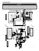
Insert a drain plug (included in parts bag) in
alternate drain fitting located on top of the
unit.
Furthermore, if the drain will not be used,
insert a second drain plug (included in
parts bag) in the drain fitting located
underneath the unit.
VO0243A
± 1"
8" MIN.
8" MAX.
VD0287
3. INSTALLATION (CONT’D)
3.8 CONNECTING THE DRAIN (CONT’D)
CAUTION