
Troubleshooting guide


VCES-DDC-IOM-1C
11
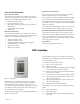
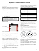
The BacStat II is the interface to the DDC. It is used to
monitor unit operation, provide maintenance/fault feed-
back and allow the user to change setpoints. It is con-
nected to terminals provided in the control panel area and
can either be mounted on the unit (indoor units only), in
the control panel area or remotely.
The display shown Figure 4 is the default display when it is
idle for several minutes.
The top characters represent the supply air temperature
leaving the unit. They also flash, once a second, when one
of these conditions occurs:
‘dF’ = Unit is in frost control mode.
‘FC’ = Unit is in free cooling mode.
‘CF’ = Wheel has failed.
‘LP’ = Low pressure alarm has tripped. Requires a manual
reset of DDC power after three failures.
‘HP’ = High pressure alarm has tripped. Requires manual
reset of pressure switch.
‘LL’ = Coil low limit sensor has tripped (supplied by others).
‘LS’ = Low supply air temperature alarm. Requires man-
ual reset of DDC power.
‘HS’ = High supply air temperature alarm. Requires man-
ual reset of DDC power.
‘OL’ = Supply/exhaust overload has tripped.
Alternatively, it can be an external unit fault (supplied by
others).
‘EF’ = Dirty exhaust filters.
‘SF’ = Dirty supply filters.
‘FS’ = Flow switch alarm or low water leaving tempera-
ture alarm.
DDC Interface
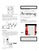
Frost Control (Selectable)
Recirculation Defrost
If the outside air temperature is below the frost control
setpoint (selectable), frost control is enabled. Frost control
timing varies depending upon strategy selected.
• Outside air damper closes.
• Recirculation damper opens.
• After delay, exhaust air damper closes and exhaust
blower stops.
• Supply blower keeps running.
• Wheel stops.
Exhaust Only Defrost
If the outside air temperature is below the frost control
setpoint (selectable), frost control is enabled. Frost control
timing varies depending upon strategy selected.
• Outside air damper closes.
• Exhaust air damper is open.
• Recirculation damper stays closed (if equipped).
• Exhaust blower keeps running.
• Supply blower stops.
• Wheel keeps running.
Preheat Frost Prevention
If the outside air temperature is below the frost control
setpoint (selectable), frost control is enabled.
If the preheater is on/off, first stage preheating is enabled.
If the outside air temperature drops below the frost con-
trol setpoint plus the differential, second stage preheating
is enabled. This process continues for the third and fourth
stages of preheating.
If the preheater is modulating, the heater elements modu-
late to maintain the frost control setpoint (selectable).
Variable Speed Defrost (VSD) Frost Prevention
The VSD frost control setting is 33°F (selectable). If the
exhaust air temperature drops below the VSD control set-
point (selectable), the wheel slows down to 30% of the
nominal speed. The wheel continues to modulate to main-
tain the frost control setpoint.
Non-defrost
No defrost strategy is implemented.
Figure 4: BacStat II