
Troubleshooting guide


VCES-DDC-IOM-1C
14
NO
T A
C
TUAL
SC
HEMATI
C
REFEREN
C
E
O
NLY
N
O
T A
C
T
U
AL
REFERENC
E
3000
3001
3002
3003
3004
3005
3006
3007
3008
3009
3010
3011
3012
3013
3014
3015
3016
3017
3018
3019
3020
3021
3022
3023
3024
From 1018
115 VAC
From 1020
Neutral
BK W
BK
FU3001
H1 H2
PNL
302
PNL
301
GY
Controls
transformer
XF3001
100 VA
X1 X2
Occ. vent
contact
by others
Unocc. recirc
contact by
others
R3006
10K
R3006A
4.99K
R3006B
2.49K
R3006C
1.24K
FW
304
FW
305
FW
305
FW
306
FW
306
FW
307
FW
307
FW
308
Y
CY
OO
GY
BL
BR
Y
Y
Y
Y
R
Y
V
Y
BR
BR
BL
V
Y
Note: Remove jumper when
OA damper actuator
end switch is installed.
Note: Remove jumper when
EA damper actuator
end switch is installed.
JP3038 JP3038
ACT4001 ACT4004
S4 S6 S4 S6
OA damper end
switch set at 90º
EA damper end
switch set at 90º
BR
PNL
309
PNL
310
PNL
310
PNL
311
R3014
10K
R3014A
4.99K
SN3008 wheel
leaving air
temperature
sensor
SN3010
outside air \
temperature
sensor
1
2
1
2
1
2
1
2
1
2
SN3012 supply
air temperature
sensor (field
installed 10
duct lengths)
SN3014 return
air temperature
sensor
SN3016 exhaust
air temperature
sensor
CBL3008
CBL3010
CBL3012
CBL3014
CBL3016 W
W
W
W
W
BK
SHLD
BK
BR
SHLD
BK
SHLD
BK
SHLD
BK
SHLD
PNL
311
PNL
311
PNL
311
PNL
313
R3018
2.49K
R3018A
1.24K
From 3001
24 VA−
From 3000
24 VA+
Option free cooling (S or D)
SN3019 outside
air humidity
sensor
SN3022 return
air humidity
sensor
Option free cooling (D)
CBL
CBL
SHLD
SHLD
R
W
BK
R
W
BK
PNL
301
PNL
301
+
0
−
+
0
−
To 2033, 3016, 3030, 4000, 5029
24 VAC+
To 3016, 3030, 4000
24 VAC−
DDC3002
24~
GND
24~
GND
Power
Power out
+
−
+
−
IP1
IP2
GND
GND
OP1
GND
OP2
GND
OP3
GND
OP4
GND
OP5
GND
OP6
GND
OP7
GND
OP8
GND
IP3
GND
IP4
GND
IP5
GND
IP6
GND
IP7
GND
IP8
GND
IP9
GND
BK
W
SHLD
BK
W
SHLD
+
+
+
+
CR3011
CR3009
CR3007
CR3013
CR3015
CR3017
COM
+ COM
+ COM
COM
COM
COM
To 3036, 4012, 4026
DDC 24 VAC+
To 3037, 4013, 4027
DDC 24 VAC−
To 3038, 4014, 4028
NET 2+
To 3039, 4015, 4029
NET 2−
Supply blower on
NO 2026
NC
Exhaust blower on
NO 2027
NC
Wheel on
NO 2028
NC
Note 1
Note 2
Note 3
OA damper
actuator
NO 4002
NC 4001
EA damper
actuator
NO 4005
NC 4004
Recirc damper
actuator
NO 4008
NC 4007
OP7 (GND)
OP7
OP7 SHLD
OP8 (GND)
OP8
OP8 SHLD
To 5023, 5030
To 5022, 5031
To 5024, 5032
To 1013
To 1014
To 1014
3025
3026
3027
3028
3029
3030
3031
3032
303
3
3034
3035
3036
3037
3038
3039
3040
3041
3042
3043
3044
3045
3046
3047
3048
3049
Option sensor contacts (D, B) Option heating (H, S) or Cooling (C)
Supply filter
switch PS3026
Exhaust filter
switch PS3026A
RY
1.6”
RY
1.6”
RB
40º
W/RW/Y BK BROO
PNL
361
PNL
362
PNL
362
PNL
363
PNL
363
PNL
364
PNL
364
PNL
365 BL
BL
V
V
V
R3028
10K
R3028A
4.99K
R3028B
2.49K
R3028C
1.24K
Low limit
thermostat
TAS3026
OL1003
OL1001
96 95
96 95
Exhaust
blower
Supply
blower
DDC3002
IP10
GND
IP11
GND
From 3000
24 VAC+
From 3001
24 VAC−
SN3033
Wheel
rotation
sensor
1
2
BK
BR
BR BL
CR2028
64
Wheel enable
Wheel rotation
board WRS3032
24 NO
NC
COMCOM
SEN
VEN
ALA
DIS
DEF+
DEF−
Option sensor contacts (W, B)
Note 1: Option outside air damper (A, B, C, D)
Note 2: Option exhaust air damper (A, B, C, D)
Note 3: Option defrost (D) or unoccupied recir
FW380O
GY
BL
BR
FW381
FW382
FW383
From 3002
DDC 24 VAC+
From 3003
DDC 24 VAC−
From 3004
NET2 +
From 3005
NET2 −
PWR 24V
COM
NET+
NET−
DC3036
BacStat II
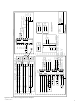
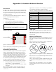
Description:
– One-speed
– VFD defrost
– DDC
– Veriable speed free cooling
Notes:
Supplied by others
Contractor installed
Contractor wiring
Requires shielded cable
Wire leader
Unit assembly (not on control panel)
Options
This drawing is the property of Venmar CES. Its content is proprietary and cannot be revealed to outside
parties without the written consent of Venmar CES.
1
#4
#1
#2
#3
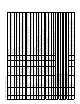
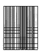
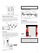
Figure A1: DDC control wiring connection example 1