
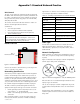
Troubleshooting guide


VCES-DDC-IOM-1C
15
NO
T A
C
TUAL
SC
HEMATI
C
REFEREN
C
E
O
NLY
N
O
T A
C
T
U
AL
REFERENC
E
#1
4000
4001
4002
4003
4004
4005
4006
4007
4008
4009
4010
4011
4012
4013
4014
4015
4016
4017
4018
4019
4020
4021
4022
4023
4024
Description:
– One-speed
– VFD defrost
– DDC
– Veriable speed free cooling
Notes:
Supplied by others
Contractor installed
Contractor wiring
Requires shielded cable
Wire leader
Unit assembly (not on control panel)
Options
This drawing is the property of Venmar CES. Its content is proprietary and cannot be revealed to outside
parties without the written consent of Venmar CES.
From 3000
24 VAC+
From 3001
24 VAC−
W/R
CR3013
CR3015
COM NC
actuator
OA damper
CR3013
COM NC
EA damper
actuator
CR3015
COM NO
EA damper
actuator
CR3017
COM NC
recirc damper
actuator
CR3017
COM NO
recirc damper
actuator
COM NO
actuator
OA damper
Note 1
Note 2
Note 3
GN/R
BK/R
GN/R
BK/R
GN/R
BK/R
GN/R
BK/R
GN/R
BK/R
GN/R
BK/R
PNL
330
PNL
331
PNL
332
PNL
333
PNL
334
PNL
335
70
(2) 6V
(1)
70
(2) 6V
(1)
70
(2) 6V
(1)
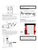
ACT4001
OA damper
actuator
No. 3012
Note: Pins CW and
CCW may be swapped
on actuator for
proper operation.
For spring return
actuators only pins
(1) and (2) are used.
ACT4004
EA damper
actuator
No. 3012
Note: Pins CW and
CCW may be swapped
on actuator for
proper operation.
For spring return
actuators only pins
(1) and (2) are used.
ACT4007
Recirc damper
actuator
No
Note: Pins CW and
CCW may be swapped
on actuator for
proper operation.
For spring return
actuators only pins
(1) and (2) are used.
Option cooling (C, I, S)
From 3002
DDC 24 VAC+
From 3003
DDC 24 VAC−
From 3004
NET 2+
From 3005
NET 2−
0
GY
BL
BR
Option cooling (I) Option cooling (I–D)
PNL
336
PNL
337
PNL
336
PNL
337
R
V
R
V
PS4017
Low pressure
control 1
Cut in = 52 psig
Cut out = 57 psig
PS4017A
Low pressure
control 2
Cut in = 52 psig
Cut out = 57 psig
Cooling override
contact by others
FW
315
FW
314 BL
BL
FW
317
FW
316 BR
BR
Dehumidification
contact by others
SN4021
Cooling leaving
air temperature
sensor
1
2
CBL4021
W
BK
SHLD
W
BK
BR
Y
0
V
Y
SHLD
DDC expander
DDC4012
~24
GND
GND
GND
GND
GND
IP1
IP2
IP3
IP4
+
+
−
GND
GND
GND
GND
OP1
OP2
OP3
OP4
~24
~24
~24
~24
~24
GND
GND
GND
IP1
IP2
+
−
GND
GND
OP1
OP2
~24
~24
CR4014
COM
+ COM
+ COM
Note 4
Cooling
stage 1
NO 2006, 4036
NC
To 4042
OP2 (24~)
To 403, 4043
OP2 (GND)
To 4037, 4044
OP2
To 5002, 5009
HGRH COM
To 5001, 5008
HGRH 0–10 VDC
CR4021
Reheat
valve
NO 2010
NC
Option cooling (I–D) / reheat (N)
4049
4048
4047
4046
4045
4044
4043
4042
4041
4040
4039
4038
4037
4036
4035
4034
4033
4032
4031
4030
4029
4028
4027
4026
4025
From 4015
OP2 (24~)
From 4016
OP2 (GND)
From 4017
OP2
0
Y
BR
BL
BL
24V
COM
0–10V
CR4039
Multi-plexing
relay
NC
COM
NO
NC
COM
NO
FW
402
FW
403
To condenser
section stage 2
To condenser
section
stage 1
Option cooling (S – 2)
Option cooling (S –1, 2)
CR4014
COM NO
Cooling
stage 1
V
V
FW
400
FW
401
From 3002
DDC 24 VAC+
From 3003
DDC 24 VAC−
From 3004
NET 2+
From 3005
NET 2−
FW
319
FW
318
Heating override
contact by others
R
R
BR
BL BL
BK
W
GY Y
0
DDC expander 2
DDC4026
Option heating (E, F, G, H, I, S, T)
CR4028
Option heating (G, E)
Heat
enable
NO 1029, 1035, 1042
NC
To 2034, 2040, 4039
Heat COM 2
To 2035, 2041, 4040
Heat staged
To 1035,1040
Heat COM
To 1034,1041
Heat 0–10 VDC
To 1036,1042
Heat SHLD
CBL4030
W
BK
SHLD
Option cooling (C)
Option heating (H, I, S, T)
From 4016
OP2 (GND)
From 4028
Heat COM 2
From 4029
Heat staged
From 4017
OP2
Y
BR
BK
W
FW
371
FW
372
FW
373
FW
3710
−
+
To chilled
water
valve
actuator
To hot
water
valve
actuator
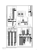
Note 1: Option outside air damper – A, B, C, D
Note 2: Option exhaust air damper – A, B, C, D
Note 3: Option defrost – D or unoccupied recirc
Note 4: Option cooling – I or S
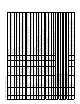
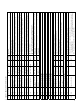
Power/Net 1
Figure A2: DDC control wiring connection example 2