Installation and User Manual VB0026 Furnace Air Exchanger with Heat Recovery CANADIAN MODELS FAE115 vFAE115 FAE115M vFAE115M US MODELS uFAE115 uFAE115M Address of your installer INSTALLER: LEAVE THIS MANUAL TO HOMEOWNER Customer Service Phone Number: 1-800-567-3855 04423 07/04/00
ABOUT THIS MANUAL This manual uses the following symbols to emphasize particular information: ! WARNING Identifies an instruction which, if not followed, might cause serious personal injuries including possibility of death. CAUTION Denotes an instruction which, if not followed, may severely damage the unit and/or its components. NOTE: Indicates supplementary information needed to fully complete an instruction. WARRANTY Venmar Ventilation Inc.
TABLE OF CONTENTS 1.0 SERVICE 1.1 1.2 Service Parts . . . . . . . . . . . . . . . . . . . . . . . . . . . . . . . . .4 Parts Ordering Chart . . . . . . . . . . . . . . . . . . . . . . . . . . .4 . . . . . . . . . . . . . . . . . . . . . . . . .4 2.0 TECHNICAL DATA . . . . . . . . . . . . . . . . . . . .4 2.1 2.2 2.3 2.4 Air Distribution . . . . . . . . . . . . . . . . . . . . . . . . . . . . . . . .4 Performance Chart . . . . . . . . . . . . . . . . . . . . . . . . . . . . .5 Dimensions . . . . . .
1.0 SERVICE 1.1 SERVICE PARTS 3 1 1 2 2 VL0004 FAE115M, uFAE115M & vFAE115M FAE115, uFAE115 & vFAE115 NOTE: Unit in normal position. Can also be installed upside down. 1.2 PARTS ORDERING CHART Number 1. 2. 3. Part Description Basic Filter Heat Recovery Core Damper Motor Part Number 04432 04433 Canada/ 04455 US 04434 2.0 TECHNICAL DATA 2.1 AIR DISTRIBUTION The Figure 1 illustrates the air flow inside units (all models).
2.2 PERFORMANCE CHART These following curves illustrate the air volume through the units for a typical installation. A typical installation is close to an exterior wall, in order to shorten the insulated duct length. On the warm air side (between the unit and the furnace), use steel rigid ducts. It is strongly recommended to minimize the number of elbows to ease air flow. See Section 3.0 and 4.0 for more details. Pressure (in. water gauge) 0.30 0.25 0.20 Stale air Fresh air 0.15 0.10 0.05 0.
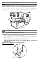
3.0 TYPICAL INSTALLATION The Figure 2 below illustrates a typical installation. The fresh air intake hood must be at least 6’ (1.8 m) away from the outdoor exhaust hood (measurement A), the fresh air from outside duct must be at least 6’ (1.8 m) away from the furnace (measurement B) and the stale air from inside duct must be at least 18” (457mm) from the furnace (measurement C). Ducts 1, 2 and 3 must be insulated. C 1 A 18" 6' 6' 3 B 2 Figure 2 VH0012 4.0 INSTALLATION 4.
4.2 CONNECTING DUCTS TO THE UNIT Insulated flexible ducts: Use the following procedure for connecting the insulated flexible ducts to the ports on the unit (exhaust to outside and fresh air from outside). a) Pull back the insulation to expose the flexible duct. b) Connect the interior flexible duct to the opening using a duct tie. c) Carefully seal the connection with duct tape. d) Pull the insulation over the joint and tuck it between the inner and outer rings of double collar.
4.4 CONNECTING THE DRAIN a) Attach the 2 plastic drain fittings to the unit using the gaskets and nuts as shown. a) VO0008 b) Cut 2 sections of plastic tubing, about 12”(305 mm) long and attach them to each drain fitting. b) 12" VO0004 c) Join these 2 short sections to the “T” junction and main tube as shown. c) VO0005 d) Make a water trap loop in the tube to prevent the unit from drawing unpleasant odors from the drain source. Make sure this loop is situated BELOW the “T” as shown.
5.0 AIR FLOW BALANCING What you Need to Balance the Unit • A magnehelic gauge capable of measuring 0 to 0.25 inches water gauge (0 to 62.5 Pa) and 2 plastic tubes. • Two flow collars (6” diameter). VP0005 Flow collar Preliminary Stages for Balancing the Unit Seal all the unit ductwork with tape. Close all windows and doors. Turn off all exhaust devices such as: range hoods, dryers and bathroom fans. Make sure balancing dampers are fully opened (F and G in Figure 5 below).
Balancing procedure 1. Set the furnace blower to high speed. 2.Place the magnehelic gauge on a level surface and adjust it to zero. 3.Connect tubing from gauge to flow collar in exhaust air stream at location A (Figure 5 on page 9). Be sure to connect the tubes to their appropriate high / low fitting. If the gauge reading drops to below zero, reverse the tubing connections. Note: it is better to start with the exhaust air flow reading because the exhaust typically has more restriction than the fresh air.
6.0 YOUR UNIT 6.1 1. 2. 3. UNIT DESCRIPTION Basic filter Heat recovery core Damper system (only on FAE115M, uFAE115M and vFAE115M units) Unit in normal position. Can also be installed upside down. 3 1 1 2 2 VL0004 FAE115M, uFAE115M & vFAE115M 6.
7.0 HOW TO OPERATE THE UNIT If you owns a FAE115,a uFAE115 or a vFAE115 model, this Section doesn’t concern your unit. Please refer to the next Sections. 7.1 INSTRUCTIONS REGARDING WALL CONTROL (FAE115M, UFAE115M AND VFAE115M ONLY) This wall control works with a dehumidistat that allows you to select the desired humidity level according to your needs. If the selector is set above the click, the unit will close its damper and stop air exchange with outside.
8.0 MAINTENANCE ! WARNING We take great care to keep sharp edges to a minimum, but please be careful when handling components. NOTE: Unit shown is in reverse position but the unit can be installed in either the “normal” or “reverse” (upside down) position. MAINTENANCE 8.1 PROCEDURE: EVERY THREE MONTHS Regular maintenance should be performed every 3 months. 1. Set the wall control to 80%. (FAE115M, uFAE115M and vFAE115M only) 2. Unlatch the door. Lift the panel towards you.
8.1 EVERY THREE MONTHS (cont’d) 6. Reinstall the components: • Heat recovery core • Filter • Door (The door is secured when you hear a click.) 7. Check the exterior air intake hood : • Make sure there are no leaves, twigs, ice or snow that could be drawn into the vent. • Clean if necessary. CAUTION Even a partial blocking of this air vent could cause the unit to malfunction. 8. Set the wall control to its previous position (FAE115M, uFAE115M and vFAE115M only). 9.