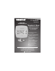
residential THERMOSTAT Digital Thermostat T1010 Single Day PROGRAMMABLE up to 2-heat & 2-cool HEAT COOL HEAT PUMP Control up to 2 Heat & 2 Cool Stages HP Stages: 2 Heat, 2 cool Single Day Programmable 4 Settings Per Day Auto Changeover 5 min.
Table Of Contents Step #1: Preparation 2 Step #2: Remove & Replace Old Thermostat 3 Step #3: Wire Connections 4 Sample Wiring Diagrams 5 Step #4: Test Operation 12 Trouble Shooting 13 CAUTION Follow Installation Instructions carefully. DISCONNECT POWER TO THE HEATER AIR CONDITIONER BEFORE REMOVING THE OLD THERMOSTAT AND INSTALLING THE NEW THERMOSTAT. WARNING Venstar Inc. 08/07 P/N T1010 This device complies with Part 15 of the FCC rules.
STEP #1 AUTO COOL 76 HEAT 68 AUTO COOL 76 PREPARATION Proper installation of the thermostat will be accomplished by following these step by step instructions. If you are unsure about any of these steps, call a qualified technician for assistance. Assemble tools.
STEP #2 AUTO COOL 76 HEAT 68 AUTO COOL 76 HEAT 68 AUTO COOL 76 HEAT 68 AUTO COOL 76 HEAT 68 REMOVE & REPLACE OLD THERMOSTAT Remove the cover of the old thermostat. If it does not come off easily check for screws. Loosen the screws holding the thermostat base or subbase to the wall, and lift away. Disconnect the wires from the old thermostat. Tape the ends of the wires as you disconnect them, and mark them with the letter of the terminal for easy reconnection to the new thermostat.
STEP #3 AUTO COOL 76 HEAT 68 WIRE CONNECTIONS If the terminal designations on your old thermostat do not match those on the new thermostat, refer to the chart below, or the wiring diagrams that follow. Wire from the old thermostat terminal marked Function G or F Fan Y1, Y or C Cooling W1, W or H Heating Install on the new thermos tat connector marked G Y1 W1,O,B Rh, R, M, Vr, A Power C Common C* R O/b Rev.
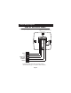
Sample Wiring Diagrams Gas or Electric Heat 5 Wire, 1 Stage Cooling, 1 Stage Gas Heat Residential Gas or Electric Heat*, Electric Cool, split systems & package units G GAS VALVE or STRIP HEAT W COMPRESSOR COMMON C FAN Y POWER R B O R G Y1 W2 W1 Y2 C * If using first stage electric heat, this option must be selected ON (see page 11, step #6 of Owner’s Manual).
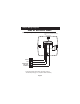
Sample Wiring Diagrams Gas or Electric Heat 4 Wire, 1 Stage Cooling, 1 Stage Gas Heat Residential Gas or Electric Heat*, Electric Cool, split systems & package units FAN G COMPRESSOR Y GAS VALVE or STRIP HEAT W POWER R B O R G Y1 W2 W1 Y2 C * If using first stage electric heat, this option must be selected ON (see page 11, step #6 of Owner’s Manual).
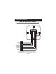
Sample Wiring Diagrams Gas or Electric Heat 6 Wire, 2 Stage Cooling, 1 Stage Gas Heat Residential two stage cooling with Gas or Electric Heat*. G COMPRESSOR COMMON Y2 C GAS VALVE or STRIP HEAT 2nd STAGE COOLING W FAN Y POWER R B O R G Y1 W2 W1 Y2 C * If using first stage electric heat, this option must be selected ON (see page 11, step #6 of Owner’s Manual).
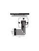
Sample Wiring Diagrams Gas or Electric Heat 6 Wire, 1 Stage Cooling, 2 Stage Heat Residential & commercial 1 Stage Cooling, with 2 Stage Gas or Electric Heat* G COMMON W 2nd STAGE HEATING GAS VALVE or STRIP HEAT W2 COMPRESSOR C FAN Y POWER R B O R G Y1 W2 W1 Y2 C * If using first stage electric heat, this option must be selected ON (see page 11, step #6 of Owner’s Manual).
Sample Wiring Diagrams Gas or Electric Heat 7 Wire, 2 Stage Cooling, 2 Stage Heat Commercial Gas or Electric Heat *, Electric Cool, split systems & package units including Commercial Heat Pumps ** G COMPRESSOR COMMON W Y2 C 2nd STAGE HEATING GAS VALVE or STRIP HEAT 2nd STAGE COOLING W2 FAN Y POWER R B O R G Y1 W2 W1 Y2 C * If using first stage electric heat, this option must be selected ON (see page 11, step #6 of Owner’s Manual).
Sample Wiring Diagrams Heat Pump 5 Wire, 1 Stage Cooling, 1 Stage Heat-Heat Pump* with O or b reversing valve**. Residential Heat Pumps, split systems & package units, with no auxiliary heat. G REVERSING VALVE** O/B COMPRESSOR COMMON C FAN Y POWER R B O R G Y1 W2 W1 Y2 C * This option must be selected ON during advanced setup (see page 11, step #4 of Owner’s Manual). ** This option must be selected O or b during advanced setup (see page 11, step #5 of Owner’s Manual).
Sample Wiring Diagrams Heat Pump 6 Wire, 1 Stage Cooling, 2 Stage Heat-Heat Pump* with O or b reversing valve**. Residential Heat Pumps, split systems & package units, with auxiliary heat. G REVERSING VALVE** O/B W2 COMPRESSOR COMMON C FAN Y POWER R B O R G Y1 W2 W1 Y2 C 2nd STAGE HEATING * This option must be selected ON during advanced setup (see page 11, step #4 of Owner’s Manual). ** This option must be selected O or b during advanced setup (see page 11, step #5 of Owner’s Manual).
STEP #4 AUTO COOL 76 HEAT 68 AUTO COOL 76 HEAT 68 AUTO COOL 76 HEAT 68 TEST OPERATION Turn the power on to the Heating/Air Conditioning system. Press the MODE button repeatedly until the HEAT icon appears on the display. Press the UP or DOWN buttons until the set temperature is 10 degrees above room temperature. The HVAC unit should energize in the heating mode. Press the MODE button repeatedly until the COOL icon appears on the display.
TROUBLESHOOTING AUTO COOL 76 HEAT 68 SYMPTOM: When using 4 wires (R, G, W, Y), the air conditioning equipment tries repeatedly to turn on, but cannot. At times the display dims or disappears. CAUSE: There is not enough power available to "power share". REMEDY: Connect a 270 ohm, 10 watt power resistor at the furnace as shown below.
TROUBLESHOOTING AUTO COOL 76 HEAT 68 AUTO COOL 76 HEAT 68 SYMPTOM: When controlling a residential heat pump, and asking for cooling, the heat comes on. CAUSE: Heat pump is not selected "ON" in the Advanced Setup. REMEDY: See page 11 of the Owner's Manual and configure step #4 to enable heat pump operation. SYMPTOM: When calling for cooling, both the heat and cool come on. CAUSE: The thermostat is configured to control a heat pump and the HVAC system is a "conventional" (non-heat pump) system.