VENSTAR FAN COIL THERMOSTAT T1075 FAN COIL THERMOSTAT 7 DAY PROGRAMMABLE 2 OR 4 PIPE SYSTEMS 3 Occupied, 1 Unoccupied Override capable 3 speed fan control Auto 2-pipe changeover when used with accessory changeover sensor Dry contact equipped Backlit display Works with most fan coil systems - 24vac Electric heat ready Non-volatile memory Dual or single setpoint Keypad lockout Remote sensor ready Display F or C OWNER’S MANUAL AND INSTALLATION INSTRUCTIONS
Table Of Contents FRONT PANEL 2 DISPLAY 3 QUICK START Set the clock and go 6 SELECTING THE HEAT OR COOL MODE 7 BASIC OPERATION 11 OVERRIDING THE DAILY SCHEDULE 12 PROGRAMMING Occupied / Unoccupied 13 ADVANCED SETUP 18 ADVANCED SETUP TABLE 24 ABOUT ADVANCED FEATURES & OPERATION 25 SAMPLE WIRING DIAGRAMS 34 WARRANTY 38 CAUTION Disconnect Power to the Heater/Air Conditioner before removing the old thermostat and installing the new thermostat.
Front Panel 1 I2:00 Am 72 Mo Mode 74 COOL AUTO 70 HEAT 2 Fan 3 4 5 1 Liquid Crystal Display 2 Up/Down Buttons 3 Mode Button 4 Fan/Override Button 5 Heat or Cool Indicator Heat = Red, Cool = Green Page 2
Display 4 2 1 3 OUTSIDE 1 1 4 1 Mode Indicators - Pages 7-10 Selects the operational mode of the equipment. HEAT - Indicates the heating mode. COOL - Indicates the cooling mode. AUTO - Indicates the system will automatically changeover between heat and cool modes as the temperature varies. PROGRAM ON - Indicates the time period program is enabled to run. OFF - Indicates heating and cooling are turned off. 2 Clock with Day of the Week - Page 6 Indicates the current time and day.
Display I2:00 6 Am Start Pm Stop 88 SuMoTuWeThFrSa Setup unoccupied 123 8 88 COOL Locked Override AUTO OUTSIDE 7 5 88 HEAT 5 Override icon - Pages 12 & 22 Indicates the program is currently being overridden for up to six hours. 6 Occupied & Unoccupied icons - Pages 13-16 Indicates the program number: Occupied 1,2,3 or Unoccupied. 7 Setup icon - Pages 18-23 Indicates the thermostat is in the advanced setup mode. 8 Fan icon - Page 11 Indicates fan operation.
Display 9 I2:00 Am Start Pm Stop 88 SuMoTuWeThFrSa Setup unoccupied 123 88 COOL Locked Override AUTO OUTSIDE 10 11 88 HEAT 9 Start & Stop icons - Pages 14-16 Appear when programming occupied time periods. 10 Locked icon - Page 31 Indicates keypad has been locked. 11 Outside icon - Page 32 Indicates the temperature displayed is from the optional outside sensor.
Quick Start Set the Clock and Go Press the MODE and FAN buttons at the same time for two seconds to enter Setup screens. During Setup and Programming: Pressing the UP or Setting the Clock DOWN button will Tip: To change modify the flashing I2:00 Am hours quickly, selection. press and hold the FAN button To adjust the and press the Clock or Day use MODE FAN Setup UP or DOWN button. Setting the Day Press MODE Mo Setup buttons.
Selecting the Heat or Cool Mode 4-Pipe Operation Select Mode by Pressing the MODE Button Heating Only The HEAT setting indicates the temperature the room has to reach before the heating source will turn on to heat the room. Cooling Only The COOL setting indicates the temperature the room has to reach before the cooling source will turn on to cool the room. Heating or Cooling AUTO will automatically select heat or cool based on room temperature demand.
Selecting the Heat or Cool Mode 2-Pipe Operation Heat Only Step #6 = 1 in the Advanced Setup section, page 19. Heating Only The HEAT setting indicates the temperature the room has to reach before the heating source will turn on to heat the room. I2:00 70 Pm Mo 68 HEAT Press Time Schedule for Heating or Cooling Program On will activate the stored timer operation for the heating and cooling setpoints (occupied or unoccupied periods).
Selecting the Heat or Cool Mode 2-Pipe Operation Cool Only Step #6 = 2 in the Advanced Setup section, page 19. Cooling Only The COOL setting indicates the temperature the room has to reach before the cooling source will turn on to cool the room. I2:00 70 Pm Mo 76 COOL Press Time Schedule for Heating or Cooling Program On will activate the stored timer operation for the heating and cooling setpoints (occupied or unoccupied periods).
Selecting the Heat or Cool Mode 2-Pipe Operation Heating and/or Cooling Step #6 = 3 in Advanced Setup (page 19), and the accessory changeover sensor (ACC-SENFC) is used. Step #6 = 4 or 5 in Advanced Setup (page 19). Operation is the same as a 4-pipe system (page 7). HEAT indicates the temperature I2:00 the room has to reach before the heating source energizes. If the Press water supply is cold, this screen and heating would be locked out.
Basic Operation Selecting Your Desired Temperature (adjusting the setpoints) AUTO OR PROGRAM MODE Pressing the UP or DOWN button when both Heat & Cool setpoints are visable will adjust both the heat and cool set temperatures simultaneously. I2:00 70 Mo Pm 76 Adjust the desired set temperature with the COOL AUTO 68 HEAT buttons. Press Fan Operation FAN Pressing the FAN button will run the fan in low, medium, or high speed continuously (see below and page 29).
Basic Operation Overriding the Daily Schedule Pressing and holding the FAN button for 5 seconds may be used to interrupt the normal time schedule programming of the thermostat. The override feature may only be used when the thermostat is running the time schedule, in Program On mode. Unoccupied Operation - During programmed, unoccupied periods pressing and holding the FAN button for 5 seconds will temporarily force the thermostat into Occupied 1 comfort settings for one to six hours (step #14, page 22).
Programming MODE Occupied & Unoccupied Periods Press the MODE button. While holding MODE, press the UP button for two seconds to enter time period programming. Select the maximum # of occupied periods to be used on any one day. Typically, most installations use only Occupied 1. (1,2 or 3) Adjust the cooling setpoint for Occupied 1. (35 - 99 ) occupied 1 Press 74 occupied 1 MODE COOL Press MODE Adjust the heating setpoint for Occupied 1.
Programming Occupied & Unoccupied Periods Adjust the heating setpoint for Unoccupied periods. (OF, 35 - 99 ) 85 unoccupied COOL 55 HEAT Press MODE Select day of the week to program. (Mo - Su) Mo occupied Press MODE 7:00 Am Start Mo occupied 1 Adjust the start time for Occupied 1. Press MODE 6:00 Pm Stop Mo occupied 1 Adjust the stop time for Occupied 1. Press MODE On Off Select Occupied 1 to run on this day (On), or not to run on this day (Off).
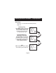
Programming Occupied & Unoccupied Periods The copy command becomes available after the maximum # of occupied periods are programmed in a day. This example uses 1 as the maximum occupied periods ever programmed in one day. Yes Select Yes or No to copy t h e p r e v i o u s d a y ’s program to this day. No If Yes is selected: Selecting Yes, then pressing mode If No is Press will copy the previous day’s program selected: MODE and then will ask the same copy question again.
Programming Occupied & Unoccupied Periods 5:00 Pm Stop Tu occupied 1 Adjust the stop time for occupied 1. On Off Yes No Select Occupied 1 to run on this day (On), or not to run this day (Off). Tu occupied 1 ON Press MODE Select Yes or No to copy the previous day’s program to this day. Co We Py If Yes is selected: Press MODE If No is Selecting Yes, then pressing mode selected: will copy the previous day’s program and then will ask the same copy question again.
Programming Occupied & Unoccupied Periods PROGRAMMING NOTES You will be prompted to enter both heat and cool setpoints even if the thermostat is configured for heat only, or cool only. If only 1 Occupied period is selected, the Occupied 2 & 3 steps will be skipped. Further, if only 2 occupieds are selected, the Occupied 3 steps will be skipped. Heat & Cool setpoints for Occupied 1 are the same for each day. Heat & Cool setpoints for Occupied 2 & 3 can be adjusted differently for each day, if desired.
Advanced Setup MODE FAN Press the MODE and FAN buttons at the same time for 10 seconds to enter Advanced Setup screens. Adjust the time of day. I2:00 Am Tip: To change hours quickly, press and hold the FAN button and press the UP or DOWN buttons. Mo NOTE: Each step # is located at the top right corner of the display for easy reference. Setup I Setup 2 Setup 3 Press MODE Select the day of the week.
Advanced Setup 4 Select Display operation: 1 = Single Setpoint 2 = Dual Setpoint See Page 33 Note: When Single Setpoint is selected, the heating or cooling setpoint will always be displayed. To display the room temperature, press and hold the MODE button for two seconds. The degree icon will blink when the large number is displaying room temperature and will remain solid when displaying the heating or cooling setpoint.
Advanced Setup Select operation when On fan is in the Auto mode: On = continuous low speed fan Off = only energize Off during a heating or cooling cycle. See Page 29, Note #2 7 AUTO Press MODE 8 Select Fan Coil Type On Off On = Carrier or IEC fan coil using a 33ZCRLYBRD relay board. Off = Conventional 3 speed fan coil system. Press See Page 33 for further explanation Adjust the deadband for the 1st stage.
Advanced Setup Step #10 will not appear if step #6 = 1 or 2. 2 Adjust the minimum difference between cooling & heating setpoints. (0 - 6 ) Setup On Select backlight operation: On - Light continuously Off - Light for 8 seconds after a button press Off Setup I0 COOL HEAT Press II MODE Press MODE C Setup I2 Select thermostat operation in degrees Fahrenheit or Celsius.
Advanced Setup Adjust the amount of time override will be active during the unoccupied time period. (0 - 6 hours) 2 00 Setup I4 Override Press MODE NO Setup Dry Contact NO = Normally Open NC = Normally Closed NC I5 Press See Page 27 MODE Occupied Select Dry Contact operation: Occupied = the thermostat will enter the Occupied mode when the Dry Unoc- Contact Contact is closed.
Advanced Setup I7 Unoccupied Setpoints 8555 Setup unoccupied Select Dry Contact Unoccupied operation: Unoccupied = when the Off Dry Contact is closed, the thermostat will control to the Unoccupied setpoints. Off = when the Dry Contact is closed, the thermostat will turn off. MODE FAN After programming is complete, press the MODE and FAN buttons at the same time to leave the Setup screens. If no buttons are pressed, the display will leave the setup screens after 60 seconds.
Advanced Setup Advanced Setups - Table Step 1 2 3 4 5 6 7 8 9 10 11 12 13 14 15 16 17 Range Description 24 Hour Time of Day Mo - Su Day of Week On / Off Display Blanking 1 /2 Single or Dual Setpoint 2/4 2 or 4 Pipe System 1-5 2 Pipe System Operation On / Off Fan Auto Operation On - Off Fan Coil Type 1-6 1st Stage Deadband 0-6 Minimum Heat/Cool On / Off Backlight F/C Degrees F or C On / Off Sensor Operation 0 - 6 Hours Override Timer Length Occ. / Unocc. Dry Contact Polarity Dry Contact Operation Unocc.
About Advanced Features & Operation CALIBRATION - Under normal circumstances it will not be necessary to adjust the calibration of the temperature sensor. If calibration is required, please contact a trained HVAC technician to correctly perform the following procedure. 1 I2:00 MODE Place the thermostat in the OFF OFF mode. 72 88 Pm Mo 2 Press and hold the MODE button. I2:00 MODE While holding the MODE button, press and hold the DOWN button for 5 seconds. All icons will appear on the display.
About Advanced Features & Operation DEADBAND OPERATION - Controls one Heat and one Cool stage with a three speed fan (see below). The low speed fan for heat or cool is turned on when: The temperature spread from the setpoint is equal to or greater than: the setpoint plus the 1st stage deadband (step #9, page 20). This 1st stage deadband is adjustable from 1-6 degrees and the default is two degrees.
About Advanced Features & Operation DRY CONTACT SWITCH - This feature allows an external device such as a Central Time Clock, Occupancy Sensor, or a Telephone activated device to force one or more thermostats into an Occupied or Unoccupied mode (steps #15 and 16, page 22).
About Advanced Features & Operation FACTORY DEFAULTS - If, for any reason, you desire to return all the stored settings back to the factory default settings, follow the instructions below. WARNING: This will reset all Time Period and Advanced Programming to the default settings. Any information entered prior to this reset will be permanently lost. 1 I2:00 MODE Place the thermostat in the OFF OFF mode. 72 88 Pm Mo 2 Press and hold the MODE button.
About Advanced Features & Operation FAN OPERATION - Fan operation is available in four different modes: Fan: When only the fan icon is displayed, this indicates that the fan is in the Auto mode, will only energize during a heating or cooling cycle, and will modulate fan speeds based on temperature demand (see page 26). Fan , Fan , or Fan : Pressing the FAN button will cause the low, medium, or high speed fan icon to appear (see page 11), indicating that the fan will run continuously.
About Advanced Features & Operation ENERGY SAVING SMART FAN - This feature automatically de-energizes the fan during an Unoccupied time period, except when necessary to heat or cool (see page 29). I2:00 70 Pm Mo unoccupied 76 COOL 68 HEAT Note: The fan will not de-energize during an Unoccupied time period if it has been programmed for continuous operation (step #7, page 20).
About Advanced Features & Operation KEYPAD LOCKOUT - To prevent unauthorized use of the thermostat, the front panel buttons may be disabled. To disable, or ‘lock’ the keypad, press and hold the MODE button. While holding the MODE button, press the UP and DOWN buttons together. The LOCKED icon will appear on the display, then release the buttons.
About Advanced Features & Operation OUTSIDE SENSOR - To view an Outside Sensor (step #13, page 21), enter the Advanced Setup by pressing and holding the MODE button. While holding MODE, press the FAN button for 5 seconds to enter Setup screens. Advance to setup step #13 by repeatedly pressing the MODE button. If an optional outside sensor is connected, the outside temperature will appear in the clock display.
About Advanced Features & Operation SINGLE SETPOINT BEHAVIOR - When configured for Single Setpoint operation (step #4, page 19), the degree icon will blink when the large number is displaying room temperature and will remain solid when displaying the heating or cooling setpoint. In the Auto and Program On modes the deadband is enforced both above and below the setpoint. To avoid short cycling, a deadband of at least two degrees is recommended (step #9, page 20).
Sample Wiring Diagram 2-Pipe, Low Voltage Valve, H2O Changeover Sensor Thermostat If 2-pipe with auxiliary electric heat R G Y1 R G3 W1 G2 EH C H2O V C 24vac 24 Volt Water Valve C R Generic Relay Board GG G2/(W) G2 G3/(Y) G3 COM COM L M H LO (L1) L1 (N/A) HI (HI) MED (MED) H2O Changeover Sensor ACC-SENFC Page 34 LO
Sample Wiring Diagram 4-Pipe, Low Voltage Valves, Duct Temperature Sensor & Dry Contact Duct Sensor ACC0402 Important Note: If a Duct sensor is connected to this thermostat it is suggested that the fan be programmed for continuous operation (step #7, page 20 of the Owner’s Manual). RS RS GND Thermostat Connect directly to R terminal on backplate.
Sample Wiring Diagram Connection Diagram for Duct Sensor to T1075 Fan Coil Thermostat Digital Sensor High Temp. Heat Shrink Tubing 5’ Plenum Rated Cable White Black RS R G Y1 G3 W1 G2 C Note: It is important to connect the black wire from the Duct Sensor directly to the R terminal on the thermostat backplate.
Sample Time Clock Wiring Diagram Important Information About: Auxiliary Input Control and Multiple HVAC Control Potential Phasing Problems CAUTION WARNING When using the auxiliary input (CK1 & R) or controlling multiple HVAC units with a single thermostat, it is possible to encounter transformer phasing problems that will interfere with thermostat operation. Connecting transformers that are not phased correctly may result in a direct short, which could damage the transformers and/or the thermostats.
Warranty One-Year Warranty - This Product is warranted to be free from defects in material and workmanship.