ColorTouch Thermostat ® Quick Start & Setup Guide
Thank You Congratulations and thank you for purchasing your new Venstar ColorTouch® Wi-Fi thermostat. This guide is intended to help you install and setup the basic features of the ColorTouch® Thermostat. For a full owners manual and installation guide, visit venstar.com. There you will also find installation and setup videos along with videos highlighting many features of the ColorTouch® thermostat. The videos can be found in the Venstar TV video series area.
Compatibility Venstar ColorTouch® Wi-Fi Thermostat is designed to work with 24V systems requiring both the R & C wires. This includes gas, electric, oil, forced air, variable speed, heat pump and radiant heat.
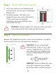
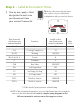
Step 1 - Power Off Current System 1) Go to your home’s circuit breaker panel and switch the furnace and air conditioner breakers off. 2) To confirm power is off, adjust the temperature on your current thermostat. If the system does not respond accordingly, power has probably been successfully shut off. WARNING: Failure to follow this step can result in personal injury and/or death from shock and electrocution. Step 2 - Remove Faceplate Remove the faceplate of current system.
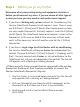
Step 3 - Before you go any further Determine what your existing wiring and equipment situation is before you disconnect any wires. If you are unsure of what type of system you have, you may need to seek professional support. A. If you have a Heating only system without Air Conditioning, the Venstar ColorTouch thermostat will require 3 wires. These 3 wires are: R (24Vac), C (24Vac) and W (Heat). Most Heating only systems use very simple thermostats that only require 2 wires the R (24Vac) and W (Heat).
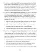
C. If you have a multi stage HVAC system comprised of a fossil fuel heater with air conditioning the Venstar ColorTouch will require the 5 wires mentioned above (R, C, W, Y, and G) plus an additional wire for each additional stage of Heating or Cooling. You may reduce the 5 wire requirement to 4 if you give up independent fan control, or use the optional accessory; Add-A-Wire. D.
MAKING 4 WIRES WORK when 5 are required (without the optional Add-A-Wire accessory) • If you have an all-electric heat system with air conditioning, this method is not an option. You must either pull new wire or use the optional Add-A-Wire accessory (ACC-0410). • If you have a single stage fossil fuel heater with air conditioning, and you would like install the Venstar ColorTouch using only 4 wires, follow the directions below.
MAKING 5 WIRES WORK when 6 are required (without the optional Add-A-Wire accessory) • If you have an all-electric heat system with air conditioning, this method is not an option. You must either pull new wire or use the optional Add-A-Wire accessory (ACC-0410). • If you have a multi stage system that requires 6 wires, and you would like install the Venstar ColorTouch using only 5 wires, follow the directions below.
Step 4 - Label & Disconnect Wires TIP: Before disconnecting any wires, take a photo of your current wire configuration with your mobile device. 1) One by one, apply a label designated to each wire you disconnect from your current thermostat. Wire from the old thermostat Function terminal marked Install on the new thermostat connector marked G or F Fan G Y1, Y Cooling/Compressor Y1 W1, W Heating W1/0/B Rh, R, M, Vr, A Power R C Common C O/B Rev.
Step 5 - Remove Current Backplate Unscrew the current backplate and remove it from the wall. Be careful not to let the wires fall into the wall. TIP: If needed, wrap the wires around a pencil or pen to keep them from falling inside the wall. Step 6 - Mount New Base 1) Gently separate the display from the base by pulling first from the bottom and then the top until the two pieces unsnap. Backplate PULL OUT WITH THUMBS IN THESE AREAS.
Wi F & P i Net ass wo wo rk rd Scr ew D rive r Pen cil (3/ Ham 16" me or r o 7/3 r D 2" d rill rill bit s) W1/O/B Y2 Y1 W2 TIP: Use pliers to straighten wire before inserting into new base. Be sure to cut any excess wire so that the insulation extends to the terminal block. When the wire is installed properly to the terminal block, there should be no copper exposed. Lev el Plie rs Thi sQ Ma uick S nua tar t l 1) Match your previous wire configuration to the new base.
Step 8 - Check Dip Switch 2 1 3 1 1 ON 2 3 2 OR O 2 OR 1 B ON 3 3 2 1 ON O HP B ELEC GAS/EL HP This dip switch configures the thermostat to control GAS/EL HP ON ON GAS/EL O GAS 3 1) Ensure which switch is correct for your system. Dip switches are located on the back of the thermostat a conventional gas/electric system or a heat pump. If your system is anything other than a heat pump, leave this switch set for GAS/EL.
Step 9 - Attach Thermostat 1) Align the pins on the thermostat circuit board with the corresponding holes below the wiring connectors and push the top and the bottom of the plastic housing enclosing the display until it clicks into place, top and bottom. Display should click into place easily. If you encounter resistance do not apply excess force – take the plate off, check that the pins are straight and ensure there are no wires in the way and retry.
Step 11 - Set Up Wi-Fi Connection (Only applies to models T7850, T7900, T8850 & T8900) Overview At minimum, the first 3 tasks below must be completed to access your thermostat remotely from a browser. The 4th step is optional (highly recommended) and only is needed to access your thermostat(s) from a mobile device. These steps are: 1. Successful connection to a local Wi-Fi Access Point with internet access. 2.
Quick Start - Connect to Wi-Fi (from initial start up) When power is connected to the thermostat and it has not been configured to connect to a Wi-Fi Access Point, the following message appears: Wi-Fi Set Up No Wi-Fi access points are configured for your thermostat. Would you like to set up one now? YES YES NO Press YES Select the access point you wish to connect to from the list. Enter the password for the Wi-Fi Access Point and press NEXT. Select automatic setup and press NEXT.
Quick Start - Connect to Wi-Fi (from menus) 72 MENU Press MENU 72 Press DOWN Press Wi-Fi • Wi Fi Setup Press Wi-Fi Setup Select the access point from the list that you want to connect to. Enter the password for the Wi-Fi Access Point and press NEXT. Select automatic setup and press NEXT. When finished, a dialog box will appear confirming the successful connection to the local Wi-Fi Access Point. Select OK, then the Wi-Fi status page will appear.
Quick Start - Connect to Skyport (from menus) Although there is more than one way to create a Skyport account, the steps below illustrate creation from a browser. If the thermostat is connected to the local Wi-Fi Access Point, but not yet joined to a Skyport account, you may join the thermostat to an account by doing the following: Select MENU from the thermostat’s home screen. Scroll down Select Skyport Select Skyport Account and follow the onscreen instructions. • Skyport Account 1.
Troubleshooting Use the following troubleshooting guide to diagnose common problems. If you are still having problems or are unsure please visit www.venstar.com/thermostats or e-mail customer service at thermostatsupport@venstar.com Problem Possible Cause Solution The air conditioning does not attempt to turn on. The compressor timer lockout may prevent the air conditioner from turning on for a period of time. Adjust the Compressor Min. Off TIme to “None”. The cooling setpoint is set too high.
Warranty One-Year Warranty - This Product is warranted to be free from defects in material and workmanship.
FCC Compliance Statement This equipment has been tested and found to comply with the limits for an intentional radiator, pursuant to Part 15, subpart C of the FCC rules. These limits are designed to provide reasonable protection against harmful interference in a residential installation. This equipment generates, uses and can radiate radio frequency energy and, if not installed and used in accordance with the instructions, may cause harmful interference in radio communications.
Cet appareil est conforme avec Industrie Canada, exempts de licence standard RSS(s). Son fonctionnement est soumis aux deux conditions suivantes: 1) ce dispositif ne doit pas causer d’interférences, et 2) ce dispositif doit accepter toute interférence, y compris les interférences qui peuvent causer un mauvais fonctionnement de l’appareil.
Patents Issued & Pending Printed on recycled paper. P/N 88-1094 Rev.