
installation instructions


Page 5L108 0817A
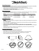
Flat Nylon Washer
Wood
Screw
Trim Piece
Countersunk
Nylon Washer
7) Install an appropriate 1/2” UL listed electrical wire clamp through each motor box electrical opening on top of the
liner. Install electrical wiring from the service panel to the liner location for each motor box. Consult the connection
diagrams (on previous page) for further details on electrical placement.
Installation Details Continued
8) Extend wires to the liner and insert them into the electrical wire clamp on each motor box. Tighten the wire clamp(s).
From inside the liner, using UL listed wire nuts, attach the “neutral” wire(s) to the white lead(s), the “hot” wire(s) to
the black lead(s), and the ground wire(s) to the green lead(s) inside the motor box(es).
Warning: Do not operate hood without proper ground connection.
9) While aligning the duct and guiding the wires, lift the liner up into the enclosure ushing the bottom edges of the liner
and the enclosure. Duct should connect together as the liner is raised into place. Note: The duct work must t inside
the exhaust collar. Wood strips may be necessary to ll any gaps between the opening and the liner if the opening in
the wood surround is larger than the liner.
10) Install a wood screw with a countersunk washer and a at
washer into each mounting hole along the bottom edge of the
liner. Note: The hardware used in this step can be found in the
liner trim kit that was previously removed from the packaging in
Step 4.
11) Install the trim piece for the back side of the liner (provided in
the liner trim kit) by hooking one side under the bottom edges
of the back countersunk washers. Snap the trim piece over the
top of the countersunk washers by applying pressure upward
and toward the liner wall. Repeat this process for the front
trim piece. After the front and back trim pieces are installed,
repeat this process for the side trim pieces. Note: It may be
necessary to lightly tap the trim piece with a rubber mallet.
12) Plug the motor(s) into the liner and reinstall the blower
motor retaining screws that were previously removed in
Step 6.
13) Replace the blower housing(s) and the blower shield(s). Make sure that the damper(s) open and close smoothly.
14) Refer to the Owner Maintenance Guide Operating Instructions for proper hood operation. Test all blower and light
functions to ensure they are operating properly.
Liner Trim Kit
Model Volts Amps Hz RPM
CFM
SP@0.0"
Equivalent CFM
•
CFM
SP@0.1"
CFM
SP@0.2"
CFM
SP@0.3"
Minimum Round
Duct Size
Sones
#
B100 Single 115 2.5 60 1550 300 450 273 245 225 6" (28 in.
2
) 5.4
B200 Dual 115 4.0 60 1550 600 900 531 480 430 8" (50 in.
2
) 6.5
B200 Dual & B100 Single 115 6.0 60 1550 900 1350 804 725 655 VP562: 10" (79 in.
2
) 6.3
Two B200 Duals 115 7.5 60 1550 1200 1800 1062 960 860 VP563: 12" (113 in.
2
) 6.6
• BecausetheMagicLung
®
blowerusescentrifugalltrationratherthanconventionalbafeormeshlters,theMagicLung
®
blowercanhandlecookingequipmentwithhighercubicfeetperminute(CFM)requirementsandcandeliverequivalentCFMmuchmore
efcientlythanotherltrationsystems.WhencomparingtheMagicLung
®
withotherblowerunitsmadebyothermanufacturers,usethe“EquivalentCFM”.
#
RatingsinaccordancewiththeStandardTestCodebytheEnergySystemsLaboratoryoftheTexasEngineeringExperimentStation.