
installation instructions

Page 5L123 0516A
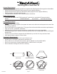
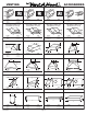
Centerline
of Hood
Centerline
of Hood
Vent Holes
Electrical (2)
11” 11”
7 ¼”
8” Transition
Opening (2)
3” Below Top
of Hood
5” x 16”
Exhaust
Opening (s)
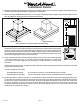
9"
16"5"
8" Round 8" Round
9"
9"
Installation Details Continued
10) While taking care to properly align the duct connection between the transition(s) and the duct(s) in the ceiling, raise
the hood to its nal position and attach it to the load-bearing framework in the ceiling using appropriate hardware or
to the duct cover(s) using the screws previously removed in Step 3.
11) From inside the hood, using UL listed wire nuts, attach the “neutral” wire(s) to the white lead(s), the “hot” wire(s) to
the black lead(s), and the ground wire(s) to the green lead(s) inside the motor box(es).
Warning: Do not operate hood without proper ground connection.
12) Plug the motors into the hood and reinstall the blower motors using the three retaining screws that were previously
removed in Step 7. Note: The side of the motor box where the “black” motors mount is labeled to ensure the motors
are installed back into the hood in the proper position.
13) Replace the blower housings and the blower shields. Make sure that the dampers open and close smoothly.
14) Refer to the Owner Maintenance Guide Operating Instructions for proper hood operation. Test all blower and light
functions to ensure they are operating properly.
Connection Diagram (60”- 66” Widths)
1100 CFM T2+200 Dual Blower
(Top View)
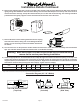
VP565 Transition
(Two included)
Transitions Installed
(Side View)