
Installation Instructions


Page 5JCH/B1 0915A
Installation Details Continued
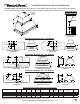
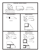
8) If the duct cover is not factory-installed on the hood, remove the duct cover from its packaging and remove the mounting
screws from the base of the duct cover. Place the duct cover on the top of the hood and secure it to the hood using
the mounting screws previously removed. Lift the hood and duct cover assembly to the location on the wall where it
will be installed and lightly mark the wall with a short, horizontal mark along the bottom edge of the hood.
9) Remove the hood and duct cover assembly from the wall. On the back side of the hood, measure the distance between
the bottom edge of the hood and the top edge of the wood mounting strip. Measure this distance above the horizontal
line made in Step 8 and lightly mark the wall with a level, horizontal line. Measure where the center (left to right) of the
hood will be and mark the upper, horizontal line on the wall with a short, vertical centerline.
10) Remove the screws inside the top of the back of the hood that retain the wood strip that is recessed in the mounting
channel. Note: Some retaining screws may be located behind the blower(s). Remove the wood mounting strip from
the back of the hood and place the top edge of the strip on the upper, level horizontal line on the wall. Referencing the
vertical centerline from Step 9, place the mounting strip on the wall so it is centered (left to right) in the space where
the hood will be located. Drill pilot holes in the strip to prevent splitting. Using proper hardware, attach the mounting
strip to at least two wall studs.
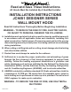
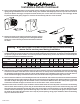
7) Install an appropriate 1/2” UL listed electrical wire clamp through each motor box electrical opening on top of the hood.
Install electrical wiring from the service panel to the hood location for each motor box. Consult the connection diagrams
(on previous page) for further details on electrical placement. Extend wire(s) to the hood. Electrical connection(s) will
occur before the hood is installed on the wall.
Warning: Make sure power is off and locked at the service disconnecting
means on the service panel during installation.
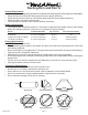
5) Remove the shipping tape that is securing the E-Z Clean shield(s) inside the hood. Remove the E-Z Clean shield(s) by
lightly pulling it toward the front of the hood. Gently close the back draft damper(s) from the top side of the hood. To
remove the blower housing(s), unsnap the suitcase latches (one on each side of the housing). The housing(s) should
be pulled forward and gently “tipped” to clear the blower wheel(s) and then out of the hood.
6) Remove the three screws retaining the blower motor(s). Unplug
and remove the motor(s), taking care not to damage the blower
wheel(s). It is not necessary to remove the blower wheel from
the motor.
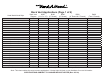
Model Volts Amps Hz RPM
CFM
SP@0.0"
Equivalent CFM
•
CFM
SP@0.1"
CFM
SP@0.2"
CFM
SP@0.3"
Minimum Round
Duct Size
Sones
#
B100 Single 115 2.5 60 1550 300 450 273 245 225 6" (28 in.
2
) 5.4
B200 Dual 115 4.0 60 1550 600 900 531 480 430 8" (50 in.
2
) 6.5
B200 Dual & B100 Single 115 6.0 60 1550 900 1350 804 725 655 10" (79 in.
2
) 6.3
Two B200 Duals 115 7.5 60 1550 1200 1800 1062 960 860 12" (113 in.
2
) 6.6
• BecausetheMagicLung
®
blowerusescentrifugalltrationratherthanconventionalbafeormeshlters,theMagicLung
®
blowercanhandlecookingequipmentwithhighercubicfeetperminute(CFM)requirementsandcandeliverequivalentCFMmuchmore
efcientlythanotherthanotherltrationsystems.WhencomparingtheMagicLung
®
withotherblowerunitsmadebyothermanufacturers,usethe“EquivalentCFM”.
#
RatingsinaccordancewiththeStandardTestCodebytheEnergySystemsLaboratoryoftheTexasEngineeringExperimentStation.