
installation instructions


Page 4JCIH/C1 0516A
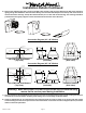
12" Round
12" Round
11 ¼"
8" Round 8" Round 8" Round
9"
16"5"
8" Round 8" Round
Centerline
of Hood
Electrical
6 ½”
Vent Holes
8” Transition
Opening
5” x 16”
Exhaust
Opening
Centerline
of Hood
Centerline
of Hood
8” Blower
Outlets
Centerline
of Hood
Electrical
6 ½”
10 ½”
Vent Holes
12” Transition
Opening
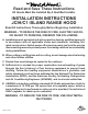
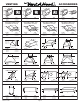
Installation Details Continued
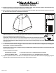
Connection Diagram (48”- 66” Widths)
Connection Diagram (36”- 48” Widths)
550 CFM T200 Dual Blower
(Top View)
1100 CFM T400 Dual Blowers
(Top View)
Transition Installed
(Side View)
VP565 Standard Transition
(Included)
VP564 Standard Transition
(Included)
Transition Installed
(Side View)
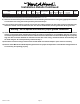
6) Remove the shipping tape that is securing the E-Z Clean shields inside the hood. Remove the E-Z Clean shields by
lightly pulling each toward the end of the hood. Gently close the back draft dampers from the top side of the hood. To
remove the blower housings, unsnap the suitcase latches (one on each side of the housing). The housings should be
pulled forward and gently “tipped” to clear the blower wheels and then out of the hood.
Warning: Make sure power is o and locked at the service disconnecting
means on the service panel during installation.
7) Remove the blower deck assembly by removing the 12 screws around the blower mounting plate. Unplug the electrical
connector(s) and set the blower assembly aside, taking care not to damage the blower wheels.
8) Install an appropriate 1/2” UL listed electrical wire clamp through the electrical strap on top of the hood deck. Install
electrical wiring from the service panel to the nal hood location. Consult the connection diagrams (above) for further
details on electrical placement.