
Installation Instruction

Page 4JDH/C1 0715B
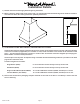
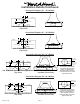
Centerline
Of Hood
Electrical
6" Outlet
Wall Side
Vent
Hole
1 7⁄8”
1 ¾”
5 ¼”
Electrical
1 ¾”
Centerline
of Hood
8” Outlet
Vent
Holes
5 ¼”5 ½”
Wall Side
Centerline
Of Hood
Wall Side
Electrical (2)
10" Outlet
Centered On
Hood Top
12 ⁄” 9 ⁄”
1 ¾”
Duct Cover
(Top of Hood)
10" Dia. or 12" Dia.
Transition Location
"Centered"
Wall Side
7"
Electrical (2)
Centerline
Of Hood
12" Outlet
Centered On
Top Of Hood
1 ¾”
16 ½”
5 ½”
1 ¾”
Duct Cover
(Top of Hood)
10" Dia. or 12" Dia.
Transition Location
"Centered"
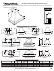
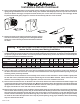
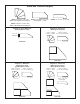
Installation Details Continued
Connection Diagram (36” - 48” Widths)
300 CFM B100 Single Blower
(Top View)
600 CFM B200 Dual Blower
(Top View)
(Front View)
(Front View)
Connection Diagram (48”- 60” Widths)
The transition shown (VP562)
is installed in the hood at the
factory as a standard item.
It will be located in the exact
center of the duct cover (left to
right & front to rear).
900 CFM B200 Dual & B100 Single Blower
(Top View)
VP562 Standard Transition
Installed (Front View)
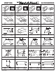
Connection Diagram (36” - 48” Widths)
Connection Diagram (54”- 66” Widths)
The transition shown (VP563)
is installed in the hood at the
factory as a standard item. It
will be located in the exact
center of the duct cover (left to
right & front to rear).
1200 CFM Double B200 Dual Blowers
(Top View)
VP563 Standard Transition
Installed (Front View)