
Product Specifications

VP562/VP563
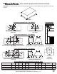
transition
centers outlet
over top of hood
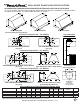
WALL MOUNT RANGE HOOD SPECIFICATIONS
DA18/DAH18/PWV18/PWVH18/XR18/XRH18/XRX18/XRXH18 “H” in part number indicates halogen
lighting. WBAR warming light bar is available on selected models. X in part number indicates 27"
depth.
*Exceeding recommended
mounting height may
compromise performance.
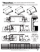
900 CFM B200 Dual & B100 Single Blower
(Top View)
1200 CFM Double B200 Dual Blowers
(Top View)
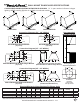
Electrical
1 ¾”
Centerline
of Hood
8” Outlet
Vent
Holes
5 ¼”5 ½”
Wall Side
11” 11”
5 ½” 5 ½”
Wall Side
5 ¼”
1 ¾”
Electrical (2)
8” Outlet
Vent
Holes
8” Outlet
Centerline
of Hood
10” Round 10” Round
8” Round
17 ½”
2”
8” Round 6” Round
12” Round 12” Round
16 ½”
8” Round 8” Round
8” Round
3”
VP562 Transition (Optional) For B300
(B200 Dual Blower & B100 Single Blower)
VP563 Transition (Optional) For B400
(Double B200 Dual Blowers)
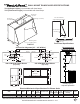
Connection Diagrams (30” - 48” Widths)
Recommended
Mounting Height*
U
L
CUS
R
10” OR 12”
Round
DA18/DAH18 PWV18/PWVH18 XR(X)18/XR(X)H18
300 CFM B100 Single Blower
(Top View)
600 CFM B200 Dual Blower
(Top View)
Electrical/Mechanical Specications For Blower Units
Model Volts Amps* Hz RPM
CFM
SP@0.0"
Equivalent CFM
•
CFM
SP@0.1"
CFM
SP@0.2"
CFM
SP@0.3"
Minimum Round
Duct Size
Sones
#
B100 Single 115 1.5 60 1550 300 450 273 245 225 6" (28 in.
2
) 5.4
B200 Dual 115 2.9 60 1550 600 900 531 480 430 8" (50 in.
2
) 6.5
B200 Dual & B100 Single 115 4.4 60 1550 900 1350 804 725 655 VP562: 10" (79 in.
2
) 6.3
Two B200 Duals 115 5.8 60 1550 1200 1800 1062 960 860 VP563: 12" (113 in.
2
) 6.6
* Add2.5ampforeachwarminglightand0.5ampforeachhalogenlight.Hoodsareavailablewithuorescentlight(oneforeachsingleordualblower)orwithhalogenlights(2lights:30"-41",3lights:42"-53",4lights:54"-66",+1lightforeach14"ifover66").
• BecausetheMagicLung
®
blowerusescentrifugalltrationratherthanconventionalbafeormeshlters,theMagicLung
®
blowercanhandlecookingequipmentwithhighercubicfeetperminute(CFM)requirementsandcandeliverequivalentCFMmuchmore
efcientlythanotherthanotherltrationsystems.WhencomparingtheMagicLung
®
withotherblowerunitsmadebyothermanufacturers,usethe“EquivalentCFM”.
# RatingsinaccordancewiththeStandardTestCodebytheEnergySystemsLaboratoryoftheTexasEngineeringExperimentStation.
SPECIFICATIONS SUBJECT TO CHANGE WITHOUT NOTICE Rev. 0210A
Connection Diagram (42” - 60" Widths)
Connection Diagram (48” - 66" Widths)