
installation instructions

Page 3TLH 0516A
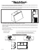
6” Outlet
Vent
Hole
3 ¼”
Electrical
Centerline
of Hood
Wall Side
1 ¾”
1 ⁄”5 ¼”
Electrical
1 ¾”
Centerline
of Hood
8” Outlet
Vent
Holes
5 ¼”5 ½”
Wall Side
Channel For Mounting Strip
13 ½” 10 ¾”
24 ¼”
Back View of Hood
12 ½”
Cut Out For
Back Vent
13 ½” 10 ¾”
24 ¼”
11 ¼”
Side View
Installation Details
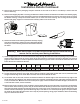
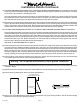
1) Read all instructions thoroughly before beginning installation. Note: These instructions apply to standard hoods only.
Custom hoods may require additional specication consideration.
2) When installing a TLH wall mount range hood, it is recommended that the bottom edge of the hood be located no more
than 23 3/4" above the cooking surface for optimum performance.
3) IF THE HOOD IS TO BE “BACK VENTED”, PROCEED DIRECTLY TO STEP 4.
Consult the connection diagrams (below) for further details on exhaust outlet placement. Install the duct from the
outside of the home to the ceiling over the exhaust outlet on the hood. The end of the duct should extend below the
cabinet or sot by 1".
Use duct tape to seal all joints. A complete listing of available Vent-A-Hood ducting materials is provided on the back
page of this instruction sheet.
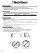
Outlet connections are as follows:
Single Blower (B100): 6" round duct or elbow will connect directly to the top of the hood.
Dual Blower (B200): 8" round duct will connect directly to the top of the hood.
A VP561 elbow and VP538 wall cap are required to back vent.
Connection Diagrams (30”- 48” Widths)
600 CFM B200 Dual Blower
(Top View)
300 CFM B100 Single Blower
(Top View)