
Installation Instructions

Page 4L122 1210A
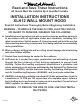
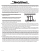
Brass Screws
A
Blower Wheel
B
Blower Housing
Installation Details Continued
5) Remove the hood from its packaging and place the back of the hood on the oor or countertop in front of the wall
where it will hang.
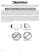
6) FOR FINISHED ROUND DUCT APPLICATIONS ONLY. FOR 10” x 10” SQUARE DUCT COVER APPLICATIONS, PROCEED
DIRECTLY TO STEP 7.
Remove the duct collar from its packaging. Discard the ceiling mounting plate. With the notched side toward the back
of the hood, place the duct collar over the top of the hood taking care to align the pins in the duct collar with the holes
on the top of the hood. From inside the duct collar, press the four pins, one at a time, into the top of the hood. Insert
the nished round duct, crimped end up, through the lower duct collar and into the exhaust collar on the hood. Seal
joint with duct tape.
7) Remove the blower shield (A) by loosening the two brass screws on the bottom of the shield. Gently close the back draft
dampers from the top side of the hood. Unsnap the suitcase latches (B) (one on each side of the blower housing). The
blower housing should be pulled forward and gently “tipped” to clear the blower wheels and then out of the hood.
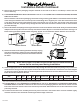
9) Install an appropriate 1/2” UL listed electrical wire clamp through the motor box electrical opening on top of the hood.
Install electrical wiring from the service panel to the hood location for the motor box. Consult the connection diagram
(on previous page) for further details on electrical placement. Extend wire to the hood. Electrical hook up will occur
before the hood is installed on the wall.
8) Remove the three screws retaining the blower motor(s). Unplug
and remove the motor(s), taking care not to damage the blower
wheel(s). It is not necessary to remove the blower wheel from
the motor.
Warning: Make sure power is off and locked at the service disconnecting
means on the service panel during installation.
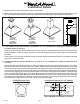
10) FOR USE WITH 10” X 10” SQUARE DUCT COVERS ONLY. IF A 10” X 10” SQUARE DUCT COVER IS NOT BEING USED,
PROCEED DIRECTLY TO STEP 11. Remove the duct cover from its packaging. Remove and save the screws from the
base of the duct cover. Place the duct cover onto the top of the hood. Attach the duct cover to the hood with the screws
previously removed.
11) Lift the hood and duct cover assembly and hold in place on the wall in the location where it will be installed. Lightly
mark the wall with a short horizontal mark along the bottom edge of the hood.
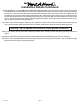
Model Volts Amps Hz RPM
CFM
SP@0.0"
Equivalent CFM
•
CFM
SP@0.1"
CFM
SP@0.2"
CFM
SP@0.3"
Minimum Round
Duct Size
Sones
#
B200 Dual 115 3.9 60 1550 600 900 531 480 430 8" (50 in.
2
) 6.5
•
Because the Magic Lung
®
blower uses centrifugal ltration rather than conventional bafe or mesh lters, the Magic Lung
®
blower can handle cooking equipment with higher cubic feet per minute (CFM) requirements and can deliver equivalent CFM much more
efciently than other than other ltration systems. When comparing the Magic Lung
®
with other blower units made by other manufacturers, use the “Equivalent CFM”.
#
Ratings in accordance with the Standard Test Code by the Energy Systems Laboratory of the Texas Engineering Experiment Station.