
Installation Instructions

Page 5L122 1210A
12) Remove the hood and duct cover assembly from the wall. On the back side of the hood, measure the distance between
the bottom edge of the hood and the top edge of the wood mounting strip. Measure this distance above the horizontal
line made in Step 11 and lightly mark the wall with a level, horizontal line. Measure where the center (left to right) of
the hood will be and mark the upper horizontal line on the wall with a short, vertical centerline.
13) Remove the screws inside the top of the back of the hood that retain the wood mounting strip that is recessed in the
mounting channel. Note: Some retaining screws may be located inside the motor box. Remove the wood mounting strip
from the back of the hood and place the top edge of the strip on the upper, level horizontal line on the wall. Referencing
the vertical centerline from Step 12, place the mounting strip so it is centered (left to right) on the wall in the space
where the hood will be located. Drill pilot holes in the wood mounting strip to prevent splitting. Using proper hardware,
attach the mounting strip to at least two wall studs.
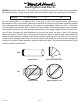
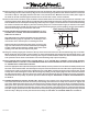
14) BACK VENTING APPLICATIONS ONLY (HOODS WITH 10” X 10”
SQUARE DUCT COVERS). IF NOT BACK VENTING, PROCEED
DIRECTLY TO STEP 15.
Note: Wall studs may interfere with back venting installations.
Additional framing may be required. It is necessary to cut a
duct access hole in the wall prior to installing the hood.
Starting 3/4” above the wood mounting strip, cut a hole 6 1/2”
high x 9” wide centered on the hood centerline (see diagram
at right). Install the duct from the outside of the home to the
opening in the wall. Use duct tape to seal joints.
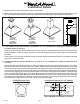
15) Hang the hood by aligning the channel at the top of the back of the hood over the wood mounting strip on the wall.
While holding the hood in place, mark locations on the wood mounting strip through the two mounting holes in the
channel at the top of the hood. Some mounting holes may be located inside the motor box. Remove the hood and drill
3/32” pilot holes at the center of the marks in the wood mounting strip to prevent splitting.
16) BACK VENTING APPLICATIONS ONLY (HOODS WITH 10” X 10” SQUARE DUCT COVERS). IF NOT BACK VENTING,
PROCEED DIRECTLY TO STEP 17 FOR FINISHED ROUND DUCT APPLICATIONS OR STEP 18 FOR TOP VENTED 10” x
10” SQUARE DUCT COVER APPLICATIONS.
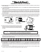
Place the appropriate elbow (Vent-A-Hood part number VP515) on the top of the hood. The elbow should be placed inside
the collar of the exhaust outlet. Use duct tape to seal joint. Insert the electrical wire from the service panel through the
electrical wire clamp on the motor box. Tighten the wire clamp. While securing the slack in the electrical wire, lift the
hood up to the wall and hang the hood on the mounting strip, taking care to properly align the duct connection between
the elbow and the duct in the wall. Secure the hood to the wood mounting strip by installing the screws (previously
removed from the strip in Step 13) into the pilot holes drilled in Step 15. SKIP STEPS 17 AND 18. PROCEED DIRECTLY
TO STEP 19.
17) FINISHED ROUND DUCT INSTALLATIONS ONLY. Remove the wire channel cover from the back of the nished round
duct. Insert the electrical wire from the service panel through the electrical wire clamp on the motor box. Tighten the
wire clamp. Guide the electrical wire into the electrical wire channel and press the wire channel cover back into place,
taking care not to pinch the electrical wire. Lift the hood into position while aligning the nished round duct and the
ceiling duct collar. As the hood is lifted into position, secure the slack in the electrical wire to ensure that the electrical
wire does not get pinched. Secure the hood to the wood mounting strip by installing the screws (previously removed
from the strip in Step 13) into the pilot holes drilled in Step 15. SKIP STEP 18. PROCEED DIRECTLY TO STEP 19.
Installation Details Continued
Back Venting Cut Out Diagram