
Installation Guide

Page 4L109 0808A
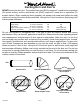
Electrical
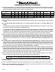
1 ¾”
Centerline
of Hood
8” Outlet
Vent
Holes
5 ¼”5 ½”
Wall Side
11” 11”
5 ½” 5 ½”
Wall Side
5 ¼”
1 ¾”
Electrical (2)
8” Outlet
Vent
Holes
8” Outlet
Centerline
of Hood
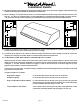
Brass Screws
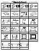
A
Blower Wheel
B
Blower Housing
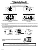
Installation Details Continued
Connection Diagrams (30”- 48” Widths)
Connection Diagram (42”- 48” Widths) Connection Diagram (48” Width)
900 CFM B200 Dual & B100 Single Blower
(Top View)
1200 CFM Double B200 Dual Blowers
(Top View)
6) Remove the hood from its packaging and place the back of the hood on the oor or countertop in front of the cabinet
where it will hang.
7) Remove the blower shield(s) (A) by loosening the two brass screws on the bottom of the shield(s). Gently close the
back draft damper(s) from the top side of the hood. To remove the blower housing(s), unsnap the suitcase latches (B)
(one on each side of the housing). The housing(s) should be pulled forward and gently “tipped” to clear the blower
wheel(s) and then out of the hood.
7) Remove the three screws retaining the blower motor(s). Unplug
and remove the motor(s), taking care not to damage the blower
wheel(s). It is not necessary to remove the blower wheel from
the motor.
Warning: Make sure power is off and locked at the service disconnecting
means on the service panel during installation.
300 CFM B100 Single Blower
(Top View)
600 CFM B200 Dual Blower
(Top View)