
Installation Guide

Page 5L109 0808A
16) Plug the motor(s) into the hood and reinstall the blower motor(s) using the three retaining screws that were previously
removed in Step 8.
17) Replace the blower housing(s) and the blower shield(s). Make sure that the damper(s) open and close smoothly.
18) Refer to the Owner Maintenance Guide Operating Instructions for proper hood operation. Test all blower and light
functions to ensure they are operating properly.
9) Install an appropriate 1/2” UL listed electrical wire clamp through each motor box electrical opening on top of the
hood. Install electrical wiring from the service panel to the hood location for each motor box. Consult the connection
diagrams (on previous page) for further details on electrical placement.
Installation Details Continued
10) Insert the electrical wire from the service panel into the electrical wire clamp on each motor box. Tighten the wire
clamp(s).
11) FOR BACK VENTING APPLICATIONS ONLY. IF NOT BACK VENTING, SKIP STEP 12. PROCEED DIRECTLY TO
STEP 13.
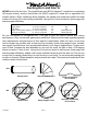
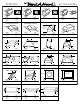
Note: Wall studs may interfere with back venting installations. Additional framing may be required. It is necessary to
cut duct access hole(s) in the wall prior to installing the hood.
To accomplish this, place the appropriate elbow(s) on the bottom of the cabinet in line with the duct hole(s) cut in Step
4. On the wall, trace around the elbow(s). Be sure to account for the wood thickness of the bottom of the cabinet when
tracing duct access holes. Remove the elbow(s) from the cabinet. Cut around the outside of the traced line(s), avoiding
wall studs. Install the duct from the outside of the home to the opening in the wall. Use duct tape to seal joints.
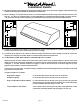
12) Pull the electrical wire slack into the cabinet while raising the hood into position. Using the four screws provided,
attach the hood to the bottom of the cabinet. Place the appropriate elbow(s) on the top of the hood. Elbow(s) should be
placed with the non-crimped end(s) on the inside the collar(s) of the exhaust outlet(s). Use duct tape to seal all joints.
Retract the electrical wire slack into the wall cavity or attic space. SKIP STEPS 13 AND 14. PROCEED DIRECTLY TO
STEP 15.
13) FOR DIRECT DUCT CONNECTIONS ONLY. IF USING TRANSITIONS PROCEED DIRECTLY TO STEP 14. Pull the electrical
wire slack into the cabinet while raising the hood into position and aligning the duct(s). The duct(s) should connect
together as the hood is located in place. Note: The duct work must t inside the exhaust collar(s). Using the four screws
provided, attach the hood to the bottom of the cabinet. Use duct tape to seal all joints. Retract the electrical wire slack
into the wall cavity or attic space. SKIP STEP 14. PROCEED DIRECTLY TO STEP 15.
14) FOR TRANSITION CONNECTIONS ONLY. Pull the electrical wire slack into the cabinet while raising the hood into position.
Using the four screws provided, attach the hood to the bottom of the cabinet. Connect the appropriate transition(s)
between the exhaust collar on the top of the hood and the duct work overhead. Note: The bottom of the transition(s)
should t inside the exhaust collar(s) on the top of the hood and on the inside of the duct work overhead. Use duct
tape to seal all joints. Retract the electrical wire slack into the wall cavity or attic space.
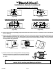
15) From inside the hood, using UL listed wire nuts, attach the “neutral” wire(s) to the white lead(s), the “hot” wire(s) to
the black lead(s), and the ground wire(s) to the green lead(s) inside the motor box(es).
Warning: Do not operate hood without proper ground connection.
Model Volts Amps* Hz RPM
CFM
SP@0.0"
Equivalent CFM
•
CFM
SP@0.1"
CFM
SP@0.2"
CFM
SP@0.3"
Minimum Round
Duct Size
Sones
#
B100 Single 115 1.5 60 1550 300 450 273 245 225 6" (28 in.
2
) 5.4
B200 Dual 115 2.9 60 1550 600 900 531 480 430 8" (50 in.
2
) 6.5
B200 Dual & B100 Single 115 4.4 60 1550 900 1350 804 725 655 VP562: 10" (79 in.
2
) 6.3
Two B200 Duals 115 5.8 60 1550 1200 1800 1062 960 860 VP563: 12" (113 in.
2
) 6.6
* Add 2.5 amps for each warming light and 0.5 amp for each halogen light.
• BecausetheMagicLung
®
blowerusescentrifugalltrationratherthanconventionalbafeormeshlters,theMagicLung
®
blowercanhandlecookingequipmentwithhighercubicfeetperminute(CFM)requirementsandcandeliverequivalentCFMmuchmore
efcientlythanotherthanotherltrationsystems.WhencomparingtheMagicLung
®
withotherblowerunitsmadebyothermanufacturers,usethe“EquivalentCFM”.
#
RatingsinaccordancewiththeStandardTestCodebytheEnergySystemsLaboratoryoftheTexasEngineeringExperimentStation.