
Installation Instructions

Page 6
JCH/C1 1213A
Installation Details Continued
11) FOR BACK VENTING APPLICATIONS ONLY. IF NOT BACK VENTING, PROCEED DIRECTLY TO STEP 12. Note: Wall
studs may interfere with back venting installations. Additional framing may be required. It is necessary to cut duct
access hole(s) in the wall prior to installing the hood.
Using the applicable venting accessories and the connection diagrams (page 4) as a guide, install the duct(s) from the
outside of the home to the wall over the exhaust outlet(s) on the hood. The end of the duct(s) should extend 1" past
the wall.
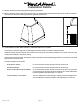
12) Hang the hood on the mounting strip by aligning the channel at the top of the back of the hood over the wood mounting
strip on the wall. While holding the hood in place, mark locations on the mounting strip through the two mounting
holes in the channel at the top of the hood. Some mounting holes may be located behind the blower(s). Remove the
hood and drill 3/32" pilot holes at the center of the marks in the wood strip to prevent splitting.
13) FOR BACK VENTING APPLICATIONS ONLY. IF YOU ARE NOT BACK VENTING, PROCEED DIRECTLY TO STEP 14.
Place the appropriate elbow(s) on the top of the hood. Elbow(s) should be placed with the non-crimped end(s) on the
inside the collar(s) of the exhaust outlet(s). Use duct tape to seal joints. Insert the electrical wire from the service panel
into the electrical wire clamp on each motor box. Tighten the wire clamp(s). While securing the slack in the wire, lift
the hood up to the wall and hang the hood on the mounting strip, taking care to properly align the duct connection(s)
between the elbow(s) on the hood and the duct(s) in the wall. Secure the hood to the mounting strip by installing the
screws (previously removed from the strip in Step 10) into the pilot holes drilled in Step 12.
SKIP STEP 14. PROCEED DIRECTLY TO STEP 15.
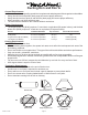
14) If applicable, install the transition on the insides of the exhaust collars and seal with duct tape.
Insert the electrical wire from the service panel into the electrical wire clamp on each motor box. Tighten the wire
clamp(s). Cut a piece of duct for each outlet of sufcient length to meet the duct(s) in the ceiling allowing room for
the transition (if applicable). If a transition is used, cut the duct to reach the transition outlet plus 1”. This will allow
the transition to engage 1” inside of the duct. See page 3 for transition heights. One end of the duct must be crimped
to t inside the duct in the ceiling. Insert the non-crimped end over the transition or into the exhaust collar(s) on the
top of the hood and seal with duct tape. While securing the slack in the wire, lift the hood up to the wall and hang the
hood on the mounting strip, taking care to properly align the duct connection(s) between the hood and the duct in the
ceiling. Secure the hood to the mounting strip by installing the screws (previously removed from the strip in Step 10)
into the pilot holes drilled in Step 12.
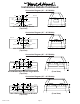
15) From inside the hood, using UL listed wire nuts, attach the “neutral” wire(s) to the white lead(s), the “hot” wire(s) to
the black lead(s), and the ground wire(s) to the green lead(s) inside the motor box(es).
Warning: Do not operate hood without proper ground connection.
16) Plug the motor(s) into the hood and reinstall the blower motor(s) using the three retaining screws that were previously
removed in Step 6.
17) Replace the blower housing(s) and the blower shield(s). Make sure that the damper(s) open and close smoothly.
18) Refer to the Owner Maintenance Guide Operating Instructions for proper hood operation. Test all blower and light
functions to ensure they are operating properly.