Ethernet and 802.11b (WiFi) Network Camera Page 1 of 69 Rev.
Table of Contents Chapter 1: Welcome to the Veo Observer ..................................................................................... 4 1.1 Package Contents............................................................................................................................... 5 1.2 Requirements ..................................................................................................................................... 6 1.3 Hardware Description and Features ..........................
Appendix F: Motion Sensor Setup................................................................................................. 59 Appendix G: Frequently Asked Questions, Troubleshooting, and Technical Support... 61 Appendix H: Estimating Bandwidth Consumption ................................................................... 64 Appendix I: Technical Specifications ........................................................................................... 65 Glossary ......................................
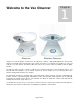
Welcome to the Veo Observer Observer 1 Chapter Wireless Observer Thank you for purchasing the Veo Observer. The Observer combines a high quality digital video camera with network connectivity and a powerful web server to bring clear video to your desktop from anywhere on your local network or over the Internet. The Wireless Observer removes the need for cables by adding an 802.11b (WiFi) interface. The Observer and your home or business network form a powerful audio/vi deo remote monitoring solution.
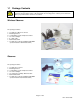
1.1 Package Contents Before installing your Observer camera, please check your package contents to ensure that all items have been included. If any of the listed items are missing, please contact your reseller from where you purchased the camera for assistance.
1.2 Requirements To connect the camera to your LAN: Wireless Observer (Infrastructure Mode) 802.11b (WiFi) Access point Wireless Observer (Ad-Hoc Mode) 802.11b (WiFi) network interface card for PC Observer Open RJ-45 port on your router/gateway To view the camera web page • Web Browser – Internet Explorer for Windows 5.
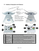
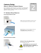
1.3 Hardware Description and Features Antenna Lens VGA CCD sensor with fixed focus lens. Microphone Monitor or record sound using the builtin microphone. Power Button Turn the camera on or off. When the power button is held down while the camera is on for 6 seconds the camera settings will reset to the factory defaults. The power button light will blink when video is being streamed.
IP Address Display IP Address LCD The LCD will indicate the last three digits of your IP Address. For example, if the IP Address “192.168.0.123” is assigned to the Veo Observer Camera, the LCD will display “123.” Refer to Section 2.2 Getting an IP address for more information.
2 Chapter Camera Setup Observer (Ethernet) Network Camera Before installing the Veo Observer Camera, you should have an available Ethernet LAN connection (RJ-45 port). To view the camera’s image or make any manual configuration changes, you will need a Windows PC with Internet Explorer 5.0 or higher, also connected to the LAN. 2.1 Hardware Setup (Observer) Connecting the Ethernet cable Step 1. Plug the included Ethernet cable into the RJ45 connector at the back of the camera as shown. Step 2.
Turning the camera on Step 5. Check that the green Ethernet status LED on the back of the camera is lit indicating a good LAN connection. The LED will blink when there’s activity. Step 4. Press the power button on the front of the camera to turn it on. The button lights up confirming that the camera is powered up. Step 6. Observe the IP address display on the lower left side of the camera. As soon as you power up your camera you’ll notice that the IP address display starts blinking.
network address is 192.168.0 and the camera display is showing 020, the IP address for the camera is 192.168.0.20 (drop leading zeros). You can easily determine your network address by checking the IP address of any PC on the network or using the Observer Setup Utility. Using the IP display to determine your camera’s complete IP Address 2.
The wireless setup dialog appears showing the camera’s current wireless settings which are the defaults. SSID (Network Name): Enter the SSID (name) of the access point to which the camera will connect. Be sure to enter the SSID exactly as it appears on your access point’s setup page. Connection Type: Select Infrastructure if the camera will connect to an access point/wireless broadband router. This is the typical setting on most home/business networks.
Step 6. Click the “Login” button to launch Internet Explorer and view the camera’s home page. Step 7. Don’t forget to add the camera’s homepage to your favorites for easy access in the future. Determining a Camera’s full IP address using the IP display Other than the last 3 digits, all devices on a LAN share the same IP address. The portion of the address common to all devices is known as the network address. Most home networks use either 192.168.0 or 192.168.1 for their network address.
Step 1. Find a suitable location to mount the camera. Step 2. Using the mounting bracket as a guide, mark the location of the two mounting holes. Step 3. Drill a ¼” hole for each screw. Step 4. Use a hammer to tap the two plastic anchors into the holes. Step 5. Use the two screws to fasten the bracket to the wall. Step 6. Place the camera on the mounting bracket platform and rotate the camera to be facing in the desired direction. Step 7.
Accessing the Camera You can access Observer cameras from any Windows PC on your LAN. There are two easy ways to access a camera, by browsing the camera’s on-board homepage using Internet Explorer or using the included PC application Veo Observer Studio. 3 Chapter The browser method does not require any special PC software other than an ActiveX control which is download and installed automatically.
3.2 Web Browser Access 1. From any PC on the local network, start Internet Explorer and enter the camera’s IP address in the address bar, as shown below, then press Enter. For help on determining the camera IP address refer to Section 2.2: Getting an IP address. 2. The first time you access the camera it will install an ActiveX control on your PC. You should see a dialog like the one shown here. If you don’t, your Internet Explorer security settings may prohibit downloading signed ActiveX controls.
5. The camera login page will appear. Type in your username and password and click Login. Note: The username and password are case sensitive. Note: If another user is currently logged into the camera you may see a message letting you know that the camera is busy. Priority is given to the highest level user. Refer to Section 3.1 Usernames and Passwords for more information. 6. Once you are logged in, the main viewing page will open and the live video will start.
The following features are available on the Live Video page: Pan/Tilt Clicking any of the yellow directional buttons will cause the camera to move one small step in that direction. Click and hold the left mouse key down to make the camera move one large step. When the camera reaches its end of travel, the buttons for that direction are grayed out and disabled. Video Window Size You can select one of the three available image sizes.
3.3 Camera Configuration Note: You must be logged in as an administrator to access the camera setup pages. 1. Click the Setup button at the top of the main page to access the configuration pages. Camera Information The following settings are found on the Camera Information page: Setting Description Camera Name A name you assign to the camera to help identify it. The name is displayed on the main page. Enter the camera location such as front door, stock room, etc.
User Accounts The User Account page is where you add and remove usernames and passwords. User accounts allow you to control access to a camera. You should change the default username and password immediately and don’t give this out to anyone. For everyone else, you should set up either User level accounts or Guest level accounts. Adding a New User Account Note: The first time you add a new account, it will automatically replace the default Admin account.
Motion Detection The camera can be triggered by a motion sensor input to send you an email with a snapshot of the current image attached. To enable this capability, check the Enable Detection checkbox and fill in the fields on the page as described below: Note: To enable motion detection you must first obtain the optional motion sensor and attach it to the motion sensor jack of the camera. Refer to Appendix F: Motion Sensor Setup for more information.
Message Any text message you wish to include in the body of the email. Reset Interval Sets the time interval, after an alert, before another detection event can occur. Video Properties Settings on this page affect the camera’s image size and quality and bandwidth consumed by the video stream. Max. Frame Rate Sets the maximum frame rate that the camera can output. Note: Actual frame rate will depend on the bandwidth (speed) of your connection.
PC Software Installation In addition to a rich web page interface, the Veo Observer includes several powerful PC applications which provide additional functionality. To install the Veo Observer Studio software: 1. Insert the Installation CD into the CD-ROM drive. The initial screen will welcome you to the installation process. Click Install to begin the software installation.
3. You’ll see the License Agreement. Please read this agreement carefully. If you agree to the License Agreement, click Yes to continue. If you do not agree and click No to the License Agreement, the software will not be installed. License Agreement Screen Choose Destination Location Screen 4. The next screen (Choose Destination Location) shows where the Veo Observer Setup Utility will be installed. Click Next.
5 Chapter Observer Setup Utility The Observer Setup Utility can be used to manually configure the camera’s network settings. It may be necessary to use the setup utility to manually assign an IP address for your camera if your network does not support DHCP. The utility is also very helpful for finding all the cameras on your network. Note: The Observer Setup Utility must be run from a PC on the local area network where the camera to be set up is located. Step 1.
Step 3. Enter the Subnet mask and Gateway. These settings should match the PC. Optionally, you may enter a camera name to help identify this camera. Step 4. Click Set. You will see a dialog prompting you to enter a username and password. You must enter a valid admin username and password. Click OK to continue. Step 5. You will see “Resetting camera…Please wait..” in the upper left corner. When the process is complete you will see “Settings saved.” Click OK to continue.
5.3 Updating the Camera’s Firmware Step 1. Visit the Observer support website to download the latest firmware (only if you are experiencing problems with your camera). Place the files on your desktop or in another folder which is easy to get to. If the files are zipped (archived), you will need to unzip them. Step 2. Run the Observer Setup Utility by clicking the desktop icon. Step 3. Select the camera’s MAC address in the list box.
6 Chapter Observer Studio PC Application Veo Observer Studio is a suite of applications designed to enhance your Observer experience. View Camera is where you can quickly connect to and control cameras on your local network or anywhere over the Internet. You can also capture snapshots and video to your PC and view up to four cameras at the same time on a single screen.
Add a Camera Click the Add button to add a camera to the list. The following window appears: Note: The information you enter here doesn’t change any of the camera’s settings. This information is kept on your PC allowing you to connect quickly and easily to any camera without re-entering the URL, port number, username, and password each time. To change a camera’s IP address or port number, use the Observer Setup Utility. To change usernames and passwords, go to the camera’s home page and click Setup.
Group Click the Group button to set up a camera group to easily log in. Once you define a group of up to four cameras, you can log in to the whole group with one click. 1. 2. 3. 4. 5. Select up to four cameras from the list on the left. Click Select to add the cameras to the group. Enter a Group Name in the text box at the top. To remove a camera from the group, select it from the list on the right and click Delete. Click OK to save the group and exit or Cancel to exit without saving.
6.3 Camera View Controls Pan and Tilt Controls: Click on any of the arrow buttons to move the camera one small step in the direction indicated by the arrow. Holding down a button for a few seconds will move the camera one large step. When the camera reaches its limit of travel range in any direction, the buttons for that direction will be disabled and their appearance will change as shown here. Note: The pan & tilt reaction time will depend on the speed of your connection.
Audio Controls Audio Level Slider: Move the slider up to increase the audio input level. Click the speaker button to enable or disable audio streaming. Enabled Note: Enabling audio will affect video performance in low bandwidth (Internet) conditions. When not using audio, be sure to leave it turned off for best video performance. Disabled Settings Only admin level user may access camera settings. The Settings button is not present when logged in as a non-admin user.
Recording a Video Note: The captured video will be the same size (resolution) as the current streaming size. Changing the display size using the image display controls does not affect the size of the captured video. Use the Settings button to change the streaming size (requires admin level user). 1. Adjust the volume using the Audio Level Slider. 2. Click [Record] to record your video. Click the Stop button any time to end recording. 3.
6.4 Using the Gallery The Gallery is an album application you use to store and access snapshots and video clips captured with Observer cameras. It can also manage other types of media for you such as sound bites and animations. Note: You must first close the View Camera window before opening the Gallery. Viewing Pictures in the Gallery 1. Click the View Gallery button. The Gallery Display Panel opens up. 2. Select a folder to view its content.
[Add A New Scene] Add a new video or picture to your movie. You can either add an existing video/picture from your computer or record a new video/picture from your Veo camera for insertion. [Add Background Music] Add music to your movie. [Remove Music] Remove music from your movie. When you are done, click Continue. Note: By default, still pictures will be shown in the movie for three (3) sec onds.
e) To send your movie to a friend: 1) Click E-mail Movie To A Friend. 2) Type in the requested information. 3) The default name given to the movie is Default.wmv. To rename the movie before sending, click on the words “Default.wmv” in the attachment text box and click [Rename]. 4) Click to send your movie. Note: Refer to Section 6.7: Configuring your E-mail Program to Send Files for instructions on how to configure your E-mail program to send movies. 6.6 Homepage Designer - Designing a Home Page 1.
[Page Link] - Link an object/image/page to another page. Linking to Another Page If you want to include a function on your page that allows you to click on a text/picture to link to other web pages, follow the steps below: a) Select the text or picture on the Main Screen that you want to link . b) Click on [Page Link]. c) Select to link to an existing page or to a page on the Internet. If linking to a page on the Internet, type in the address (URL) of the website, then click OK.
7. Select the background music. Click [Set Background Music]. 8. Choose your background music. To listen to the music before selecting, place your cursor on clicking. You may click without [Mute] to turn the background music on and off. Note: When you change the Mute button to , it does NOT remove the background music. You just will not be able to hear it. To remove the music entirely, click [Set Background Music] and choose . After you select your music, click Continue. 9.
Applying Text, Images, Videos, and Animated Characters Adding and Editing Text a) Click [New Text] to add new text to the scene/page. b) Double-click on the text to edit it. A screen similar to the one below appears: Preview font Type text in here Select font color Apply effects to fonts Select font The following are the application buttons and their description: [Insert Video] - Insert a new video clip. [Insert Image] - Insert a new image.
When you click , the following box appears: Adding Sound Effects to an Animated Character You can add a sound effect to an animated character either by inserting a .wav file from the Sound Effects folder and then click . Note: Sound Effects are only applied when the animated character is moving along its defined path. If you have not defined a path, the sound effect will be disabled. Defining the Path of an Animated Character (also works with a still picture).
6.7 Configuring your E-mail Program to Send Files In order to send your files directly from the Veo Observer Studio, you must change your default mail agent, otherwise known as Messaging Application Program Interface (MAPI). For E-mail programs that do not support MAPI (i.e. AOL, web-based E-mail programs), you need to attach the files manually. For further assistance on how to attach files to your E-mail, contact your E-mail or web-based E-mail provider. Using MAPI with Microsoft Outlook Express 1.
3. Under "E-mail" select the e-mail provider that you normally use to send e-mail. (i.e. America Online, Hotmail, Yahoo! Mail) Note: If you do not see America Online, Hotmail, or Yahoo! Mail listed under the “E-mail” section, you’ll need to install the latest version of America Online (if using America Online [http://www.aol.com]) or MSN Messenger (if using Hotmail [http://messenger.msn.com]) or Yahoo! Messenger (if using Yahoo! Mail [http://messenger.yahoo.com]).
Accessing Cameras Over the Internet If your home or business LAN is connected to the Internet through a high speed (broadband) Internet connection, with at least 128 kbps upload bandwidth, you can access your cameras by web browser from anywhere on the Internet. To do this you need to: 1. 2. 3. 7 Chapter Know your WAN (Internet) IP address. This is the IP address that your Internet Service Provider gives you to access the Internet.
7.3 Port Forwarding All TCP/IP (Internet) networking uses software ports. Ports can be thought of as channels on your television. By default, all web page traffic is on channel (port) 80. By default, the Observer uses port 80 to deliver its web page to your browser and port 1600 to send video. Therefore, both of these channels (ports) must be open (not blocked by your router/firewall) to incoming traffic in order for you to connect to the camera from the Internet.
You camera is now live on the Internet. Browsing your camera from the Internet is the same as browsing on your LAN except that you must enter your WAN IP address (or camera domain name if you’ve set up a DDNS service) instead of the LAN IP address. 7.5 Accessing Multiple Cameras over the Internet When accessing multiple cameras over the Internet, you must assign separate port numbers for each camera. The reason for this is simple.
The Internet uses DNS servers to lookup domain names and translate them into IP addresses. Domain names, such as www.veo.com, are just easy to remember aliases for IP addresses. A dynamic DNS service is unique because it provides a means of updating your IP address so that your listing will remain current when your IP address changes. There are several excellent DDNS services available on the Internet and best of all most are free to use. Two such services you can use are www.no-ip.com and www.DynDNS.org.
Restoring Factory Default Settings Press and hold the Power button down for 6 seconds to reset the camera to the factory defaults. You will see “300” displayed in the IP Address LCD display to indicate that the camera has been reset. Release the Power button to reset the camera. A Appendix Note: You will need to reconfigure your camera settings after resetting the camera. The Veo Observer will revert back to the factory default username (admin) and password (password) if the camera is reset.
External Microphone If you would like to use an external microphone (not included), you can attach any standard 1/8” (3.5 mm) microphone to the Veo Observer’s external microphone connection port located on the rear of the camera. Using an external microphone will automatically disable the camera’s built-in microphone. The use of an external microphone is recommended in noisy areas or if the camera is located far away from the audio source.
C Appendix Network Utilities Microsoft Windows includes various network information utilities to determine various network configurations. To determine your IP address and network settings, follow the steps below, depending on your operating system. C.1 Determining your IP Address and Network Settings Windows 98/Me: 1. Click on Start->Run and type in: command and then press ENTER 2. In the MS-DOS window, type in: winipcfg and then press ENTER 3.
3) If there is a camera, or a PC or other network device online and using this address you will see: Pinging 123.123.123.123 with 32 bytes of data: Reply from 123.123.123.123: bytes=32 time<1ms Reply from 123.123.123.123: bytes=32 time<1ms Reply from 123.123.123.123: bytes=32 time<1ms Reply from 123.123.123.123: bytes=32 time<1ms TTL=128 TTL=128 TTL=128 TTL=128 Ping statistics for 123.123.123.
Router Configuration The following section describes the initial configuration of the router and port forwarding for some of the most common routers from 3Com, Belkin, D-Link, Linksys, Microsoft, NETGEAR, Proxim, Siemens, and SMC. D Appendix In order to access the Veo Observer/Wireless Observer from the Internet, you’ll need to configure your router to use ports 80 and 1600 (default settings).
54g Wireless DSL/Cable Gateway Router - [F5D7230-4] 1) Log into your router. 2) On the main page, select Firewall on the left side of the page. 3) Under Firewall, select Virtual Servers. 4) Enter the following information on the page: Line #1: Enable: Checked in Description: VeoWeb Internet Port: 80 to 80 Type: TCP Private IP address: Type in the camera's IP address. (Look on the Observer’s IP Address LCD display for the last 3 digits of the camera’s IP address.
For ID #1: Service Port: 80 Server IP: Type in the camera's IP address, for example: 192.168.0.3 Enabled/Disabled: Enabled For ID #2: Service Port: 1600 Server IP: Type in the camera's IP address, for example: 192.168.0.3 Enabled/Disabled: Enabled 4) Save your settings. The Observer should now be configured to work with your router and be accessible from the Internet. DI-714 1) Log into your router. 2) On the main page, click on Advanced Settings at the top of the page.
Enable: Checked in 5) Click on Apply to save the settings. The Observer should now be configured to work with your router and be accessible from the Internet. Microsoft (http://www.microsoft.com/hardware/broadbandnetworking ) Wired Base Station - [MN-100] Wireless Base Station - [MN-500] 1) Log into your router. 2) Open the Base Station Management Tool, and then click Security. 3) On the Security menu, click Port Forwarding, and then click Set up persistent port forwarding.
5) Click Apply to save the settings. The Observer should now be configured to work with your router and be accessible from the Internet. Proxim (http://www.proxim.com) ORiNOCO BG-2000 Broadband Gateway 1) Log into your router. 2) On the router's main page, click on Setup at the top of the page. 3) On the left side of the page, click on Advanced Settings->Port Forwarding. 4) Check in the checkbox for Enable Port Forwarding. 5) Click New on the right side of the page.
5) Under PC (Server), select your camera or the camera's IP address from the list. If the camera is not listed, select the link titled "My PC is not listed." 6) Leave Protocol as TCP. 7) Under Internal Port No type in: 80 8) Under External Port No type in: 80 9) Click on Add to save these settings. 10) Under the first box, next to the Enable checkbox, type in: VeoCam. 11) Under PC (Server), select your camera or the camera's IP address from the list.
5) Click Apply to save the settings. The Observer should now be configured to work with your router and be accessible from the Internet. SMC7004AWBR - Barricade 4-Port 11Mbps Wireless Broadband Router 1) Log into your router. 2) Click on Virtual Server on the left side of the page. 3) Enter the following information on the page: For ID #1: Service Port: 80 Server IP: Type in the camera's IP address. (Look on the Observer’s IP Address LCD display for the last 3 digits of the camera’s IP address.
Internet Explorer Security Settings The Veo Observer web page communicates with the camera using a combination of JavaScript and an ActiveX control. The ActiveX control must be downloaded from the camera and installed on your PC. There are four things that your Internet Explorer security settings must allow for the web page to work correctly. 1. 2. 3. 4. E Appendix Download signed ActiveX controls Run ActiveX controls and Plug-ins Script ActiveX controls marked safe for scripting Active Scripting.
F Appendix Motion Sensor Setup By connecting the optional motion sensor to the camera’s motion sensor jack, you can enable motion detection alert emails with an attached image. After connecting the sensor as shown, you must configure the camera’s motion detection settings. Refer to Section 3.3 Camera Configuration of the User’s Guide for further information. Please visit http://www.veo.com/observer for information on purchasing the optional motion sensor.
1. 2. 3. 4. 5. Locate the motion sensor connector at the rear of the camera. The holes for inserting the sensor wires are labeled 1 through 4 from left to right. Use a small screwdriver to depress and latch down the orange tabs over holes 1, 2 and 4. Insert the red wire into hole #1 until the insulation just reaches the back of the camera. Use the screwdriver to press down and release the orange tab above hole #1 locking the wire in place.
Frequently Asked Questions, Troubleshooting, and Technical Support Problem or Question What username and password do I use the first time I access the camera or after a factory default reset? What do I do if I can’t remember my username and password? The IP display continues to blink 000 and doesn’t show an address after 1 minute. The IP display blinks “---“ (Wireless Observer only) The camera’s welcome page does not appear when I try to browse the camera.
The camera cannot be pinged. Internet Explorer displays the following message: “Your current security settings prohibit downloading ActiveX controls”. Internet Explorer shows: “Error on Page” in the status bar in the lower left corner of the webpage. How can I tell if the camera’s ActiveX is installed on my PC? The camera ActiveX does not install properly or cannot be installed. When trying to log in to the camera, this message appears: “Another user is already logged onto the camera.
Performance Issues Slow frame rate Blank screen or very slow video when audio is enabled Image is noisy or grainy Audio is choppy Pan/Tilt does not respond quickly Your connection to the camera does not have enough bandwidth to support a higher frame rate for the streamed image size. Try reducing the video streaming size to 160x120 or 320x240 and/or disabling audio. Audio will consume 128 kbps and audio is always given priority over video. Disable audio to improve or restore video.
Estimating Bandwidth Consumption Here is a guide to help you understand the bandwidth requirements for your camera. H Appendix Bandwidth is equal to the average frame data size in kilobits multiplied by the average frame rate in frames per second. Frame data size, or the number of bits comprising a single video frame varies a great deal from depending on scene complexity and lighting conditions. This is due to the variable nature of JPEG image compression. Shown below are some average figures.
Technical Specifications I Appendix Veo Observer Network Camera Technical Specifications Image Lens Pan-Tilt Network Connection Audio Power Environmental WLAN Resolution Type Color depth Streaming Sizes Compression VGA (640 x 480) CCD 24 bit 160 x 120, 320 x 240, 640 x 480 Motion JPEG (in hardware) 160 x 120 10 fps Frame rate 320 x 240 10 fps 640 x 480 5 fps Sensitivity 1 lux Aperture F2.
Glossary Term Explanation 802.11b IEEE standard for wireless networking devices. Ad-Hoc Peer to peer network. Method for directly connecting devices on a wireless network to each other without an access point. Each device must use a static IP. DDNS DHCP Display size Relates to camera how Dynamic Domain Name System. DNS service which self-updates periodically to deal with changing IP addresses. Dynamic Host Configuration Protocol.
SSID Service Set Identifier. A unique name shared among all devices on a wireless network. The Wireless Observer uses this setting to determine which network to connect to. SMTP Simple Mail Transfer Protocol. The camera sends email with this protocol. TCP/IP URL WAN WAN IP address WAP Transmission Control Protocol/Internet Protocol. The most common communication protocol for Ethernet networking and all of the Internet. Uniform Resource Locator.
Warranty Veo Statement of Limited Warranty Veo warrants this product to be free from defects in material and workmanship for a period of (2) years from the date of original purchase. If this product proves to be defective in material or workmanship during the warranty period, Veo will, at its sole option, repair or replace the product with a similar product. Replacement product or parts may include remanufactured or refurbished parts or components.
Exclusion of damages: VEO'S LIABILITY IS LIMITED TO THE COST OF REPAIR OR REPLACEMENT OF THE PRODUCT. VEO SHALL NOT BE LIABLE FOR: • • • DAMAGE TO OTHER PROPERTY CAUSED BY ANY DEFECTS IN THE PRODUCT, DAMAGES BASED UPON INCONVENIENCE, LOSS OF USE OF THE PRODUCT, LOSS OF TIME, LOSS OF PROFITS, LOSS OF BUSINESS OPPORTUNITY, LOSS OF GOODWILL, INTERFERENCE WITH BUSINESS RELATIONSHIPS, OR OTHER COMMERCIAL LOSS, EVEN IF ADVISED OF THEIR POSSIBILITY OF SUCH DAMAGES.