24 GHz NB Radar Sensor User Manual Product Model: NB24G175V3 Veoneer US, Inc.
Table of Contents 1 ABBREVIATIONS 3 1.1 LIST OF TERMINOLOGY AND ACRONYMS 3 2 PRODUCT OVERVIEW 3 2.1 2.2 PRODUCT DESCRIPTION PRODUCT APPLICATION EXAMPLES 3 3 3 TYPICAL INSTALLATION 4 4 HARDWARE DESCRIPTION 5 5 SENSOR GENERIC SPECIFICATIONS 6 6 SENSOR FEATURES 6 7 CONFORMANCE STATEMENTS 7 7.1 7.2 7.3 USA CANADA EUROPE 7 7 7 8 REVISION HISTORY 7 Table of Figures FIGURE 1: TYPICAL INSTALLATION POSITIONS ............................................................................
1 Abbreviations 1.1 List of Terminology and Acronyms BSD CAN DSP EMC FM GHZ HP LCA MMIC MCU NB PCB RADAR RCTA RF Blind Spot Detection Controller Area Network Digital Signal Processor ElectroMagnetic Compliance (regulatory standards) Frequency Modulation Giga-Hertz (10^9) Host Processor Lane Change Assist Monolithic Microwave Integrated Circuit MicroController Unit Narrow Band Printed Circuit Board RAdio Detection And Ranging Rear Cross Traffic Alert Radio Frequency (or Microwave) 2 Product Overview 2.
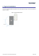
3 Typical Installation The radar is typically installed in the positions of the vehicle depicted in Figure 1 often mounted behind a bumper or emblem.
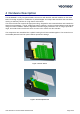
4 Hardware Description The NB RADAR is a fully integrated 24GHz radar sensor with both RF and DSP modules on the same PCB. The design supports a combination of pulsed Doppler and chirped FM waveforms that can detect moving or stationary vehicles in a high clutter environment. The sensor’s DSP side controls all signal processing, diagnostics and communications and contains the sensor’s two processors. The RF module generates, transmits, receives and demodulates radar signals using two Veoneer MMICs.
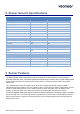
5 Sensor Generic Specifications Sensor Specifications & Functions Value Unit Frequency Band 24.05 – 24.25 GHz Power Dissipation <5 W Vehicle Network Interface CAN2.0B Operating Temperature -40C to +85 C Input Operating Voltage 8 – 16 V RF Output Power 13.5 dBm peak Operating Life 15 years Operating Conditions Waveform Parameters Cycle Time 80 ms Bandwidth <200 MHz Size 95x63x16.
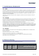
Conformance Statements 7.1 USA This device complies with Part 15 of the FCC Rules. Operation is subject to the following two conditions: (1) this device may not cause harmful interference, and (2) this device must accept any interference received, including interference that may cause undesired operation. CAUTION TO USERS Changes or modifications not expressly approved by the party responsible for compliance could void the user`s authority to operate the equipment.