
Installation Guide


PRO-LINE GATE KIT
For Vinyl & Wood Gates
1
Before you begin...
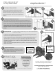
Unpack and familiarize yourself with the contents of this kit. All components are illustrated
in the figures above.
2
Determining Gate Size & Post Spacing
3
End Cap Installation
Screws
Included:
18 #12 Flat Head/Self
Drilling 1.5” Long Screws
for Adapters
8 #14 Pan Head
1.5” Long Screws
for mounting plates
16 #12 Pan Head/Self
Drilling 1.5” Long Screws
for Endcaps
Glue (1)
Determining Gate Size: First, determine the proper size of your new gate. You can
convert a whole fence panel into a gate using the Pro-Line Gate Kit, or you can
customize the size of your panel to any desired size (see figure 2a). It is very important to
make any desired alterations to the panel before continuing the installation process.
Post Spacing: Once you have determined the width of your gate, you must make sure
your posts are properly spaced. Your gate posts should be placed about 2” wider than
your gate panel (1.5” minimum, 3” maximum) to allow for hinge adjustments (see figure
2b). Example: If your gate panel is 36” wide, your posts should be placed 38” apart
(inside dimension). Both posts should be plumb and level.
If you are using wood panels proceed to step 4.
Once you have your desired size panel, you must install all 4 Endcaps prior to
installing your hinges. Proper installation of the 4 Endcaps is vital, as they will add
extra strength and stability to your fence panel, required to work with your hinges.
For each Endcap, apply glue to the fingers of the Endcap and insert into the fence
rail. Next, using the 16 provided #12 Pan Head / Self Drilling 1.5” long screws, secure
the curved end of the Endcap to the rail sections of your fence panel as shown in
figure 3a. *Note: Make sure the screws pass through the horizontal rail, the end
cap, and the vertical post to stabilize your panel.
*Note: Each Endcap
requires 4 screws (two per
side). The screws are to
be secured to the corners
of the fence panel to
ensure they catch the
bottom fingers of the
Endcaps. Be sure to
alternate your screw
placement to avoid the
screws hitting each other
inside the fence panel.
Figure 3b illustrates proper
screw placement with the
black dots representing
one side and the shaded
dots for the opposite.
Recommended screw
placements are 1” and 3”
from the end of your
fence panel.
Assembly Instructions
For Single & Double Gates Cont.
Endcaps (4)
Hinge
Assembly (2)
Adjustment
Screw
Tension
Adjustment
Slide Plates (2)
4
First determine wether
you want your gate to swing into
or out of your property. Refer to
figures 4a & 4b and mount the
hinges to your gate as shown.
Determine
Gate Swing
Direction
4a 4b
Inward Swing Direction Outward Swing Direction
er
Adjustable Latch (1)
with Fasteners (See Page 3 for
Installation)
See figure 3a.
Hole
Placement
Example
3b
The easiest way to do this is to take
a piece of 4x8 plywood on two saw
horses. Screw a 2x4 up the 8’ side
of the plywood and 2x4 at the 4’
side. This should create a 90 degree
corner to square your gate against.
*Tip: Most contractors install the end caps on a table that has a square corner to use.
3a
2a
2b