
User's Manual
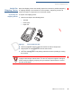
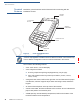

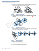
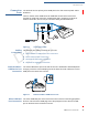
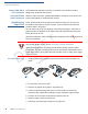
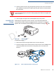
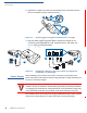
Table Of Contents
- C680
- Contents
- Preface
- Terminal Overview
- Setup
- Terminal Location
- Inside the Shipping Carton
- Terminal Features
- Installing the SIM/SAM/R-UIM/ Micro-SD Cards
- Connection Ports
- Installing the Paper Roll
- Installing the Dongle
- Power Supply
- Using the Battery
- Battery Behavior (No Power Pack)
- Charging the Battery
- Conducting Smart Card Transactions
- Using the Magnetic Card Reader
- Conducting a Contactless Transaction
- Wireless Transactions
- Bluetooth Transactions
- 3G and CDMA Connectivity
- Dial-up/Ethernet Connectivity
- Periodic Inspection
- Specifications and Maintenance
- Verifone Service and Support
- Troubleshooting Guidelines
- Contact Verifone

S
ETUP
Connection Ports
C680 I
NSTALLATION
G
UIDE
17
R
A
F
T
R
E
V
I
S
I
O
N
B
.
6
Connection
Ports
The terminal has one primary micro-USB port on the side used for power and/or
download.
There is another micro-USB connector USB Host located at the back of the
terminal for peripheral connection. Powered RS-232 is supported via RJ11 for
modem connection, and via a 4-pin connector debug and OS download.
Figure 8 Connection Ports
Cabling
Connections
The following are cabling scenarios for your unit:
1
Dedicated Micro-USB Device Port Connection
2
Micro-USB Host Port Connection.
3
Powered RS-232/4-Pin Connection.
4
Powered RS-232/RJ11 Connection
Dedicated Micro-
USB Device Port
Connection
The micro-USB Device port on the side of the unit is dedicated to download/power
charging. Insert the micro-USB plug end of the Host connector cable to the micro-
USB port on the terminal to connect.
Figure 9 Dedicated Micro USB Device Port
Micro-USB Host
Port Connection
The micro-USB Host port on the back of the unit is used for connecting peripheral
devices. Insert the micro-USB plug end of the pheriperal cord to the micro-USB
port on the back of the terminal to connect.
4 PIN WIRE