Vx810 Installation Guide VeriFone Part Number 24963, Revision B
Vx810 Installation Guide © 2008 VeriFone, Inc. All rights reserved. No part of the contents of this document may be reproduced or transmitted in any form without the written permission of VeriFone, Inc. The information contained in this document is subject to change without notice. Although VeriFone has attempted to ensure the accuracy of the contents of this document, this document may include errors or omissions.
CONTENTS PREFACE . . . . . . . . . . . . . . . . . . . . . . . . . . . . . . . . . . . . . . . 3 Audience. . . . . . . . . . . . . . . . . . . . . . . . . . . . . . . . . . . . . . . . . . . . . . . . . . . . . . . . Organization . . . . . . . . . . . . . . . . . . . . . . . . . . . . . . . . . . . . . . . . . . . . . . . . . . . . . Related Documentation . . . . . . . . . . . . . . . . . . . . . . . . . . . . . . . . . . . . . . . . . . . . Guide Conventions . . . . . . . . . . . . . . . . . . . . . . . .
C ONTENTS CHAPTER 4 Maintenance and Clean the PIN Pad. . . . . . . . . . . . . . . . . . . . . . . . . . . . . . . . . . . . . . . . . . . . . . . 25 Cleaning Card Readers . . . . . . . . . . . . . . . . . . . . . . . . . . . . . . . . . . . . . . . . . . . . . . . . . . . 25 CHAPTER 5 Service and Support Service Returns . . . . . . . . . . . . . . . . . . . . . . . . . . . . . . . . . . . . . . . . . . . . . . . . . 27 Accessories and Documentation . . . . . . . . . . . . . . . . . . . . . . . . . . . . .
PREFACE This guide is the primary source of information for setting up and installing Vx810. Audience This guide provides simple descriptions of Vx810 features, as well as basic information for the installation and configuration of the Vx810. Organization This guide is organized as follows: Chapter 1, Overview. Provides an overview of the Vx810. Chapter 2, Setup. Explains setup and installation of Vx810, selecting a location and establishing connections with other devices. Chapter 3, Specifications.
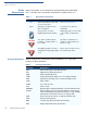
P REFACE Guide Conventions Guide Conventions Various conventions are used to help you quickly identify special formatting. Table 1 describes these conventions and provides examples of their use. Table 1 Convention Document Conventions Meaning Example Blue Text in blue indicates terms that are cross references. See Guide Conventions. Italics Italic typeface indicates book titles or emphasis. You must not use this unit underwater. NOTE The pencil icon is used to highlight important information.
P REFACE Guide Conventions Table 2 Acronym Definitions (continued) Acronym Definitions GID Group Identifier - Concept inherited from Verix terminals file system HDLC High-level Data Link Control ICC Integrated Chip Card (Smart Card) LCD Liquid Crystal Display MAC Message Authentication Code, as defined in ANSI X9.
P REFACE Guide Conventions 6 VX810 INSTALLATION GUIDE
CHAPTER 1 Overview This chapter provides a brief description of VeriFone’s Vx810. Vx810 PIN pad The Vx810 is a PIN pad with an integrated smart card reader for connection to either VeriFone transaction terminals or third party electronic point-of-sale systems, offering advanced security and smart card processing capabilities. The Vx810 series supports both symmetric encryption algorithms (DES, 3DES, and AES) and asymmetric encryption (RSA).
O VERVIEW Features and Benefits Features and Exceptional Ease of Use Benefits • Bold, ergonomic design is sleek, stylish, and lightweight for conveniently handing the unit to the consumer for PIN entry or other input. • Intuitive telco-style interface and large, colored control keys simplify training and reduce support requests. • Highly readable display handles multiple languages for global applications.
CHAPTER 2 Setup This chapter describes the setup procedure for Vx810, in the following sections: Select Location • Select Location • Unpack Shipping Carton • Examine Vx810 Features • Install/Replace MSAM Cards • Privacy Shield • Cable Connections • Power Supply • Smart Card Reader Use • Magnetic Card Reader Use Use the following guidelines to select a location for the Vx810. Ease of Use • Select a location convenient for both merchant and cardholder.
S ETUP Unpack Shipping Carton Electrical • Considerations • • Avoid using this product during electrical storms. Avoid locations near electrical appliances or other devices that cause excessive voltage fluctuations or emit electrical noise (for example, air conditioners, electric motors, neon signs, high-frequency or magnetic security devices, or computer equipment). Do not use the Vx810 near water or in moist conditions.
S ETUP Examine V x 810 Features Examine x V 810 Features Before you continue with the installation process, familiarize yourself with the Vx810 features: FUNCTION KEYS DISPLAY ALPHA KEY TELCO KEYPAD ATM STYLE KEYS MAGNETIC CARD READER COLOR-CODED FUNCTION KEYS (OPTIONAL) Figure 2 SMART CARD READER (OPTIONAL) Vx810 Features The Vx810 includes the following features: • A display. • Three types of keys: • Keypad matrix for four ATM-style keys and four Function keys.
S ETUP Install/Replace MSAM Cards Install/Replace MSAM Cards You may need to install one or more multiple security access module (MSAM) cards or replace the old cards. CAUTION Observe standard precautions in handling electrostatically sensitive devices. Electrostatic discharges can damage the equipment. VeriFone recommends using a grounded anti-static wrist strap. To change or install 1 MSAMs Remove the data cable from the back of the unit.
S ETUP Install/Replace MSAM Cards 5 Install the MSAM card by aligning the card to match the embossed number and carefully sliding it into the slots until fully inserted. Figure 5 MSAM Insertion 6 Close the MSAM compartment door and tighten the locking screw.
S ETUP Privacy Shield Privacy Shield This figure shows an example of a Vx810 with the privacy shield installed.
S ETUP Cable Connections Connection to The Vx810 connects to a VeriFone terminal via a straight cable. There is a another VeriFone minimum power requirement for the Vx810, currently specified as 3.5W. In cases Terminal where the terminal is only able to provide a 7 V DC output to power the Vx810, the terminal must be able to source at least 0.5 A of current. Otherwise, proper functioning of the Vx810 is not guaranteed.
S ETUP Cable Connections Direct USB Similarly, a dongle cable is required in standard USB environments. For this cable Connection option, the host end has a molded housing which exposes the standard USB plug. Figure 10 Direct USB Connection USB–Download This cable option comes with a junction box that provides a mini-style Type B USB Support using an socket for connecting to the USB-based host and a DC jack for external power External Power connection.
S ETUP Power Supply Ethernet Connection with External Power Brick The cable required junction box that provides a standard RJ-45 LAN socket and a DC jack. However, since most hosts do not support peer-to-peer LAN connection to a PIN pad, an additional RJ-45 socket is provided on the junction box to allow a direct connection between Vx810 and the host.
S ETUP Smart Card Reader Use Smart Card Reader Use The smart card transaction procedure can vary depending on the application. Verify the proper procedure with your application provider before performing a smart card transaction. To Conduct a Smart 1 Card Transaction Position the smart card with the gold contacts facing upward (see Figure 14). 2 Insert it into the smart card reader slot in a smooth, continuous motion until it seats firmly.
S ETUP Contactless Module Contactless Module The Vx810 supports contactless smart card transactions through the Vx810 CTLS module. The SD card slot at the back of the Vx810 serves as the expansion port for installing the module as an add-on to the traditional magnetic card reader. Installing the Vx810 To install the Vx810 CTLS module: CTLS Module 1 Place the device facedown on a soft, clean surface to protect the lens from scratches.
S ETUP Contactless Module 5 Slide the tabs on the narrow end of the metal plate down to engage the ears of the Vx810. 6 Carefully hold both devices and the metal plate in place. Screw fine-thread black machine screw into the Vx810 first. Next, install the 3 coarse-thread self taping screws into the Vx810 CTLS module.. Figure 18 Installing the Screws WARNING Be careful. The self taping screws will require a moderate amount of force to install.
S ETUP Contactless Module Using the Vx810 The Vx810 CTLS module is only active when signaled by an application for the CTLS Module conduction of a contactless smart card transaction. To perform a contactless smart card transaction: 1 Gently tap the card onto or hold the card (within to 4 cm.) against the surface of the RFID canopy. 2 An activated LED visual on the RFID canopy accompanied by a short beeping sound indicates a successful transaction.
S ETUP Contactless Module 22 VX810 INSTALLATION GUIDE
CHAPTER 3 Specifications This chapter discusses power requirements, dimensions, and other specifications of the Vx810. Unit Power • Requirements • Power Pack • 9 - 12 V DC minimum of 450 mA 5 V DC minimum of 500 mA (USB power) CPS11212-3A-R • UL, ITE listed, Class 2, switching power supply • PS, 12.
Specifications 24 VX810 INSTALLATION GUIDE
CHAPTER 4 Maintenance and Cleaning The Vx810 has no user-serviceable parts. Clean the PIN Pad To clean the unit, use a clean cloth slightly dampened with water and a drop or two of mild soap. For stubborn stains, use alcohol or an alcohol-based cleaner. For best results, use a Verifone Cleaning Kit (refer to the Accessories and Documentation section). CAUTION Never use thinner, trichloroethylene, or ketone-based solvents – they can deteriorate plastic or rubber parts.
M AINTENANCE AND C LEANING Card Readers 26 VX810 INSTALLATION GUIDE
CHAPTER 5 Service and Support For Vx810 problems, contact your local VeriFone representative or service provider. For Vx810 product service and repair information: Service Returns • USA – VeriFone Service and Support Group, 1-800-834-4366, Monday - Friday, 8 A.M. - 8 P.M., eastern time. • International – Contact your VeriFone representative. Before returning the Vx810 to VeriFone, you must obtain a Merchandise Return Authorization (MRA) number.
S ERVICE AND S UPPORT Service Returns • NOTE You will be issued MRA number(s) and the fax will be returned to you. One MRA number must be issued for each Vx810 you return to VeriFone, even if you are returning several of the same model. 5 Describe the problem(s) and provide the shipping address where the repaired or replacement unit must be returned. 6 Keep a record of the following items: • Assigned MRA number(s).
S ERVICE AND S UPPORT Accessories and Documentation Accessories and Documentation VeriFone produces accessories and documentation for the Vx810. When ordering, please refer to the part number in the left column. VeriFone Online Store at www.store.verifone.com • USA – VeriFone Customer Development Center, 1-800-834-4366, Monday - Friday, 7 A.M. - 8 P.M.
S ERVICE AND S UPPORT Accessories and Documentation 30 VX810 INSTALLATION GUIDE
CHAPTER 6 Troubleshooting Guidelines This chapter lists typical examples of malfunctions that you may encounter while operating your Vx810 and the steps that you can take to resolve them. The troubleshooting guidelines provided in the following section are included to assist successful installation and configuration of the Vx810. If you are having problems operating your Vx810, please read these troubleshooting examples.
TROUBLESHOOTING G UIDELINES Transactions Fail To Process Transactions Fail To Process There are several possible reasons why the unit may not be processing transactions. Use the following steps to troubleshoot failures. Check Magnetic Card Reader • Perform a test transaction using one or more different magnetic stripe cards to ensure the problem is not a defective card. • Ensure that you are swiping cards properly (see Magnetic Card Reader Use).
TROUBLESHOOTING G UIDELINES Transactions Fail To Process VX810 INSTALLATION GUIDE 33
VeriFone, Inc. 2099 Gateway Place, Suite 600 San Jose, CA, 95110 USA Tel: (800) VeriFone (837-4366) www.verifone.