M424 Installation Guide Verifone Part Number DOC380-003-EN-A , Revision A.
M424 Installation Guide © 2020 Verifone, Inc. All rights reserved. No part of the contents of this document may be reproduced or transmitted in any form without the written permission of Verifone, Inc. The information contained in this document is subject to change without notice. Although Verifone has attempted to ensure the accuracy of the contents of this document, this document may include errors or omissions.
CONTENTS P R EF AC E . . . . . . . . . . . . . . . . . . . . . . . . . . . . . . . . . . . . . . . 5 Audience. . . . . . . . . . . . . . . . . . . . . . . . . . . . . . . . . . . . . . . . . . . . . . . . . . . . . . . . Organization . . . . . . . . . . . . . . . . . . . . . . . . . . . . . . . . . . . . . . . . . . . . . . . . . . . . . Related Documentation . . . . . . . . . . . . . . . . . . . . . . . . . . . . . . . . . . . . . . . . . . . . Guide Conventions . . . . . . . . . . . . . . . . . . . . . .
C ONTENTS C H AP T ER 3 Specifications Power Rating . . . . . . . . . . . . . . . . . . . . . . . . . . . . . . . . . . . . . . . . . . . . . . . . . . . 31 Power Pack . . . . . . . . . . . . . . . . . . . . . . . . . . . . . . . . . . . . . . . . . . . . . . . . . . . . Temperature . . . . . . . . . . . . . . . . . . . . . . . . . . . . . . . . . . . . . . . . . . . . . . . . . . . . External Dimensions. . . . . . . . . . . . . . . . . . . . . . . . . . . . . . . . . . . . . . . . . . . . . . Weight . . .
PREFACE This guide is the primary source of information for setting up and installing the Verifone M424 device. Audience Organization This guide is useful to anyone installing and configuring the device. This guide is organized as follows: Chapter 1, Device Overview. Provides an overview of the Verifone M424 device. Chapter 2, Setup. Explains setup and installation of the device, selecting a location, and establishing connections with other devices. Chapter 3, Specifications.
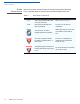
P REFACE Guide Conventions Guide Conventions Various conventions are used to help you quickly identify special formatting. Table 1 describes these conventions and provides examples of their use. Table 1 Convention Meaning Example Blue Text in blue indicates terms that are cross references. See Guide Conventions. Italics Italic typeface indicates book titles or emphasis. You must not use this unit underwater. The pencil icon is used to highlight important information.
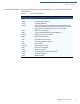
P REFACE Guide Conventions Acronym Definitions Acronyms are used in place of the full definition. Table 2 presents acronyms and their definitions. Table 2 Acronym Definitions Acronym Definitions AES Advanced Encryption Standard Algorithm ARM Advanced RISC Machine CTLS Contactless Reader DUKPT Derived Unique Key Per Transaction Method as defined in the VISA’s POS Equipment Requirement: PIN processing and Data Authentication, International Version 1.
P REFACE Guide Conventions 8 M424 INSTALLATION GUIDE
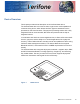
CHAPTER 1 Device Overview This chapter provides a brief description of the Verifone M424 device. The Verifone M424 device is a best-in-class, single-screen media-capable and consumer-facing device, which allows electronic payment transactions to be processed in multi-lane scenarios. This payment processing solution with a fully integrated POS can scan barcodes, QR codes and products with the help of integrated camera.
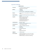
D EVICE O VERVIEW Key Features and Benefits M424 Features Processor • 1.1 GHz, Arm Cortex-A7 quad-core • Dedicated secure processor Memory • 2 GB RAM • 16 GB Flash • Secure processor: 512 MB DRAM, 512 MB Flash Display • 5.5 inch (120.77 X 67.93) HD IPS LCD, Capacitive Touch screen Keypad (touch) • Dedicated mechanical keypad and on-screen (touch) keypad.
D EVICE O VERVIEW Features and Benefits Features and Benefits Following are the features and benefits. Exceptional Ease of • Use Large 5.5” LCD display for unlimited application possibilities and easy readability under various lighting conditions. • Touchscreen for icon-based applications or electronic signature capture support. • Intuitive telco-style keypad with colored control keys. • Bi-directional magnetic stripe card reader with an extended blade for optimal card reading.
D EVICE O VERVIEW Features and Benefits 12 M424 INSTALLATION GUIDE
CHAPTER 2 Setup This chapter describes the setup procedure for: Device Location • Device Location. • Inside the Shipping Carton. • Device Features. • Connection Ports. • M424 Connection Options. • MSAM Card. • Device Power Source. • Smart Card Reader. • Magnetic Card Reader. • Contactless Smart Card Transaction. • M424 Wi-Fi/BT Support. • Optional Accessories. The following are guidelines used to select an ideal location for the device.
S ETUP PIN Protection Measures • Electrical • Considerations • Do not use the device outdoors. Avoid using this product during electrical storms. Avoid locations near electrical appliances or other devices that cause excessive voltage fluctuations or emit electrical noise (for example, air conditioners, electric motors, neon signs, high-frequency or magnetic security devices, or computer equipment). • Avoid using the device near water or in moist conditions.
S ETUP Inside the Shipping Carton The following table describes the two preferred mounting methods and the recommended measures to protect against PIN capture in four observation corridors: Table 3 Mounting Methods and Protection Measures Customer in Queue Customers Elsewhere On-site Cameras Use signage behind the PED Install so that customer is between PED and next in queue No action needed Do not install within view of cameras No action needed Install so that customer is between PED and next in
S ETUP Inside the Shipping Carton 2 Validate the authenticity of the sender by verifying the shipping tracking number and other information located on the product order paperwork. 3 Remove and inspect the contents of the shipping carton. The device ships in multiple configurations, the carton may include all or any of the following: NOTE • Device • Connectivity cable • Additional accessories Power supply and connectivity cables are shipped separately or depending on the customer requirements.
S ETUP Inside the Shipping Carton If any device is found to have been tampered with, please remove it from service immediately, keep it available for potential forensics investigation, and notify your company security officer and your local Verifone representative or service provider. To contact Verifone, please see Service and Support. For terminals equipped with a privacy shield, perform daily inspections to ensure that the privacy shield is installed and has not been removed.
S ETUP Device Features Device Features Familiarize yourself with the device features before continuing with the installation process: 4/5#( 3#2%%. $)30,!9 #4,3 0!9-%.4 :/.% ,%$3 4/ ).$)#!4% #!2$ 37)0% 2%!$9 !5$)/ *!#+ -!'.%4)# #!2$ 2%!$%2 3-!24 #!2$ 2%!$%2 #!-%2! 3#!..%2 4%,#/ 349,% +%90!$ Figure 2 M424 Features Front Panel The front panel offers the following features: • The Verifone M424 device has a colored touch screen Display.
S ETUP Connection Ports Connection Ports The device has one custom multiport interface for power and communications connection. Connecting Cables To connect required cable connections and other devices: and other Devices 1 Unscrew and remove cable cover as shown below. Figure 3 Removing Cable Cover 2 Connect required cable connections or optional devices. Attaching the multiport cable provides multiple connection options.
S ETUP Connection Ports 3 Close cable compartment as shown below.
S ETUP M424 Connection Options M424 Connection Options The M424 device can be connected to other systems using several methods. They all connect to the M424 using the Multiport cable connected on the rear of the unit. Powered Multiport Powered Multiport Cable provides USB signal connectivity and power. It provides Cable a convenient way of connecting other systems of the same type.
S ETUP Device Power Source 3!- 3!- 2 1 3!- 3!- Figure 7 NOTE MSAM Insertion Position the card’s gold contacts facing downward toward the user. The card slot in the device has a set of contacts. The MSAM card has a notch on one corner to ensure that it fits into the connector base in only one way. To replace SAM card, gently slide out the old SAM card before inserting a new one. Device Power Source The device is powered by an external AC/DC power pack.
S ETUP Smart Card Reader 2 Close cable cover. 3!- 3!- 3!- 3!- Figure 8 Connecting Base Cable to Device 3 Plug in power supply to the power connection port on the base module. 4 Plug the AC power cord into a wall outlet or power surge protector. Smart Card Reader The smart card transaction procedure can vary depending on the application. Verify the proper procedure with your application provider before performing a smart card transaction.
S ETUP Contactless Smart Card Transaction Using the Smart Card To use the smart card reader (credit/debit card transaction): Reader (Credit/Debit Card Transaction) 1 MSR indicator lights will flash when ready to accept MSR transaction. 2 Position a magnetic card with the stripe to face downward, as shown in Figure 10. 3 Swipe the card through the magnetic card reader.
S ETUP Optional Accessories Wireless M424 supports wireless transactions. Wireless transactions occur when initialized Transaction by an application. Optional Accessories These accessories can be used to further enhance the device’s functionality. See Chapter 2, section Accessories and Documentation for list of part numbers for additional information. Privacy Shield The privacy shield is used to deter the visual observation of PIN values as they are being entered by the cardholder during a transaction.
S ETUP Optional Accessories Figure 14 Privacy Shield attached to Device Stand A mounting device that serves as the device’s docking station and adds support during customer PIN-entry. The stand can be positioned on a countertop and can be adjusted during transactions for privacy.
S ETUP Optional Accessories Docking the Device To dock the device on the stand: on the Stand 1 Place the device on the base. Ensure that the stand screws align with the keyholes found at the back of the device. Figure 16 Docking Device onto the Stand 2 Slide down device to lock in place.
S ETUP Optional Accessories 1 Slide the device upward to unhook the device from the stand. Figure 18 Undocking Device from the Stand 2 Lift device off the stand. Figure 19 NOTE Lifting Device off the Stand When conducting customer transactions, the stand orientation can be adjusted for convenience and security.
S ETUP Accessories and Documentation Accessories and Documentation Verifone produces the following accessories and documentation for the M424. When ordering, please take note of the part number. • Verifone online store at www.estore.verifone.com • USA – Verifone Customer Development Center, 1-800-Verifone (837-4366), Monday - Friday, 7 A.M. - 8 P.M., Eastern time • International – Contact your Verifone representative Accessories Below are accessories used with your device.
S ETUP Accessories and Documentation 30 M424 INSTALLATION GUIDE
CHAPTER 3 Specifications This chapter discusses power requirements, dimensions, and other specifications of the device. Power Rating • Power Pack • 12 V DC, 1 A PWR445-001-01-A • UL/cUL, ITE listed, LPS power supply • Input rated: 100-240 V AC, 50/60 Hz • Output rated: 12 V DC, 1 A, 12 W Temperature • External • Dimensions • • Weight • Processors • • Memory • Operating temperature: -0° to 50° C (32° to 122° F) Length: 178.85 mm (7.04 in) Width: 169 mm (6.66 in) Depth: 28.45 mm (1.
S PECIFICATIONS MSAM Card Reader MSAM Card • Reader Two Security Access Modules (SAMs) card slots. Integrated • Contactless Reader ISO 14443, ISO 18092, EMV Keypad • • Three color-coded function keys below the keypad Audio Jack • 3.5 mm headphone jack Peripheral Ports • Custom Multiport Cable Security • 32 12-key Telco-style keypad M424 INSTALLATION GUIDE Complies to PCI-PTS 5.x requirements, as well as many regional security requirements.
CHAPTER 4 Maintenance and Cleaning The M424 device has no user-maintainable parts. It can, however, be cleaned. General Care Your device is a product of superior design and craftsmanship and should be treated with care. The following suggestions will help you protect your warranty coverage. • Keep the device dry. Precipitation, humidity, and all types of liquids or moisture can contain minerals that will corrode electronic circuits.
M AINTENANCE AND C LEANING Additional Safety Information These suggestions apply equally to your device, or any of its attachments or accessories. If your device is not working properly, take it to the nearest authorized service facility for servicing or replacement. For your safety, have this device serviced only by a Verifone-authorized service provider. Additional Safety Information The following are additional safety information in using this device.
M AINTENANCE AND C LEANING Additional Safety Information Magnetic Stripe The Magnetic Stripe Reader (MSR) must be cleaned on a regular basis (daily to Cleaning once a week, depending on usage), as dirt accumulation can lead to MSR reading problems. MSR can be cleaned using commercially available card reader cleaning cards or using recommended Verifone cleaning card (PN 02746-02).
M AINTENANCE AND C LEANING Additional Safety Information 36 M424 INSTALLATION GUIDE
CHAPTER 5 Service and Support Contact your local Verifone representative or service provider for any problems on your device. For product service and repair information: Service Returns NOTE • USA – Verifone Service and Support Group, 1-800-837-4366, Monday - Friday, 8 A.M. - 8 P.M., Eastern time. • International – Contact your Verifone representative. You must obtain a Merchandise Return Authorization (MRA) number before returning the device to Verifone.
S ERVICE AND S UPPORT Service Returns • NOTE Reference the model and part number in the Note box One MRA number must be issued for each device you return to Verifone, even if you are returning several of the same model. 3 Describe the problem(s). 4 Provide the shipping address where the repaired or replacement unit must be returned. 5 Keep a record of the following items: 38 M424 INSTALLATION GUIDE • Assigned MRA number(s).
CHAPTER 6 Troubleshooting Guidelines This chapter lists typical examples of malfunctions that you may encounter while operating your device and the steps that you can take to resolve them. The troubleshooting guidelines provided in the following sections are included to assist successful installation and configuration of the device. Please read these troubleshooting examples if you are having problems operating your unit.
TROUBLESHOOTING G UIDELINES Blank Display Blank Display When the device display is blank: • If the device display is dark, tap the screen with the stylus or your finger. If the unit was in screen-saver mode, the screen will turn on when touched. • If the display does not show correct or readable information, check all cable connections. If the problem persists, contact your local Verifone representative for assistance.
Verifone, Inc. 1-800-Verifone www.verifone.com M424 Installation Guide Verifone Part Number DOC380-003-EN-A, Revision A.