MX 900 Series D R AF T Installation Guide
AF T R D
MX 900 Series Installation Guide Part Number SPC132-022-01-A, Revision A March 1, 2012 VeriFone®, Inc. 2099 Gateway Place Suite 600 San Jose, CA 95110 Telephone: 408-232-7800 http://www.verifone.com Printed in the United States of America. © 2012 by VeriFone, Inc.
AF T R D
Contents 1. Introduction. . . . . . . . . . . . . . . . . . . . . . . . . . 1 Intended Audience . . . . . . . . . . . . . . . . . . . . . . . . . . Document Organization . . . . . . . . . . . . . . . . . . . . . . . Modifications to this document . . . . . . . . . . . . . . . . . . . . Acronyms, Abbreviations, and Definitions . . . . . . . . . . . . . 1 1 1 2 2. Hardware Installation . . . . . . . . . . . . . . . . . . . 3 D R AF T Installing the Device . . . . . . . . . . . . . . . . . . . . . . . .
ii MX 900 Series Installation Guide Cleaning the Terminal . . . . . . . . . . . . . . . . . . . . . . . . . . Cleaning the Display Screen . . . . . . . . . . . . . . . . . . . . . . Magnetic Stripe Cleaner. . . . . . . . . . . . . . . . . . . . . . . . . Smart Card Reader . . . . . . . . . . . . . . . . . . . . . . . . . . . . 25 25 25 25 4. Terminal Specifications . . . . . . . . . . . . . . . . . . 27 D R AF T Terminal Specifications . . . . . . . . . . . . . . . . . . . . . . . . .
1 INTRODUCTION This installation guide is your primary source of information for setting up and installing the MX 900 Series terminals, the MX 915™ and MX 925™. Intended Audience This guide is useful for anyone installing and configuring the MX 900 Series terminals. A basic description of terminal features is also provided.
2 MX 900 Series Installation Guide Acronyms, Abbreviations, and Definitions The following table describes the common acronyms, abbreviations, and definitions used: Meaning BFI Buffer Flush Interval bps bits per second CRC Cyclic Redundancy Check FA File Authentication Firmware Software in FLASH/ROM FTP File Transfer Protocol GISKE Global Interoperable Secure Key Exchange IPP ISR JFFS2 KLK KSN KVC LED Internal PIN Pad Interrupt Service Routine Journaling Flash File System VSS Key Loadin
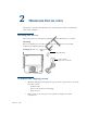
2 HARDWARE INSTALLATION This chapter describes the MX 900 Series installation procedures and includes connection examples. Installing the Device This section presents installation guidelines for the MX 900 Series terminal. AF T Unpacking Open the shipping carton and carefully inspect the contents for possible tampering or shipping damage. Warning:Do not use a damaged terminal. Power Pack (Separate Carton) D R Berg Retainer To unpack the shipping carton 1.
4 MX 900 Series Installation Guide 3. Place the components on a table or countertop. 4. Save the shipping cartons and packing material for repacking or moving in the future. Selecting a Location Warning:The MX 900 Series terminal is designed for indoor use only. Use the following guidelines to select a location for the MX 900 Series terminal. 1. Select a location for the terminal that offers adequate ventilation and protection and is convenient for the user and merchant. AF T 2.
MX 900 Series Installation Guide 5 Warning:Do not use the MX 900 Series terminal near water, including a bathtub, wash bowl, kitchen sink, or laundry tub. Do not use in a wet basement or near a swimming pool. 3. Before connecting the terminal to the power pack, complete the installation by connecting all the cables (see Connecting the Device and Power Up with the Multiport Cable). Stand Mount In most retail spaces, the terminal is positioned on a stand mount.
6 MX 900 Series Installation Guide Wall Mount The MX 900 Series terminal can be mounted on a wall. To wall mount the MX 900 Series terminal: 1. Create a template of the three key hole slots on the bottom of the MX 900 Series terminal. AF T Key Hole Slots Mounting Holes R 2. Locate a wall stud to base center placement of the MX 900 Series terminal unit. 3. Mark the hole placement on the desired wall location. D 4. Prepare holes for screw placement.
7 MX 900 Series Installation Guide PIN Protection Measures The following techniques can be employed to provide for effective screening of the PIN-entry keypad during the PIN-entry process. These methods would typically be used in combination, though in some cases a method might be used singly. Positioning of terminal on the check-stand in such a way as to make visual observation of the PIN-entry process infeasible. Examples include: – Visual shields designed into the check-stand.
8 MX 900 Series Installation Guide Installing Optional Components This section discusses the installation procedures for the optional components available for the MX 900 Series terminal. Your terminal may already have some of these options, as modules can be installed at the factory or in the field. Installing Countertop Wedge The countertop wedge raises the rear section of the MX 900 Series terminal by an angle of 10 degrees to facilitate use of the screen.
9 MX 900 Series Installation Guide Removing or Installing the I/O Module Use the following steps to remove and install I/O modules. AF T Tabs D R Push down the two tabs so that the I/O module can slide out.
10 MX 900 Series Installation Guide Slide the module in until it locks into place.
MX 900 Series Installation Guide 11 AF T 3. Remove the card compartment door screw and rotate the door up and back to access the SD and MSAM cardholders. D R 4. Remove any previously installed MSAM or SD card by sliding the card from the cardholder.
12 MX 900 Series Installation Guide Note: Before inserting the SD or MSAM card, position it with the card’s gold contacts facing the smart card reader end of the terminal. The cardholder connector base has a set of contacts and a notch on one corner to ensure the card is positioned correctly. The card has a notch on one corner to ensure that it fits into the connector base in only one way. The card compartment door will not close properly if the cards are installed incorrectly. D R AF T 5.
MX 900 Series Installation Guide D R AF T 6. Reinstall the compartment cover and door screw.
14 MX 900 Series Installation Guide Installing the Stylus and Holster D R AF T Use the following steps to install the stylus and its holster. 1. Turn the MX 900 Series terminal over and plug the stylus cable into the top of the terminal and insert and tighten screw.
MX 900 Series Installation Guide 15 D R AF T 2. Locate the two screw holes for attaching the holster. Route the stylus cable through a channel in the holster and then attach the holster using the two screws. The cable should be in the channel between the holster and the terminal.
16 MX 900 Series Installation Guide Removing the Privacy Shield To remove the privacy shield, pull on each side of the privacy shield until it disconnects from each of the three connection points. Warning: Once the privacy shield is removed, it cannot be re-installed.
17 MX 900 Series Installation Guide Connecting the Device This section provides brief descriptions of possible MX 900 Series terminal device connections and the power pack connection. For complete information about installing and using an optional device, see the user documentation supplied with that device. Ensure that the multiport cable or I/O module is not connected to a power pack before attaching to the MX 900 Series terminal.
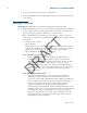
18 MX 900 Series Installation Guide Example of connections to the I/O Module (I/O Module 2 shown below) Berg USB Multiport Cable Audio Ethernet COM2 AF T Power The MX 900 Series terminals use a multiport cable to make the following connections: ECR ■ Ethernet LAN ■ Development/host PC ■ Serial cable ■ USB ■ USB device R ■ Power input ■ Audio output D ■ Note: Some multiport cables require additional cabling to work; for example a pigtail for certain ports or Ethernet cable.
MX 900 Series Installation Guide 19 Caution: Improper installation or removal of the terminal connector may AF T permanently damage the MX 900 Series terminal. The following precautions must be taken with multiport cables: Use the Ethernet port on the IO module only if the multiport cable is not attached. Otherwise, use the Ethernet port on the multiport cable. ■ Do not force the terminal connector into place.
20 MX 900 Series Installation Guide Connecting ECR in Tailgate Mode To connect an ECR to the MX 900 Series terminal, insert the multiport cable plug into the bottom socket on the terminal and install the retainer. Then connect the RS485 tailgate connector to the desired 12-volt port on the back of the IBM register, such as 9A or 9B. Caution: Use caution because the various ports on the back of the register AF T have different voltages.
MX 900 Series Installation Guide 21 Connecting to a Host PC R AF T To connect the MX 900 Series terminal to a development PC, which shows a USB connection with the 23741-02-R multiport cable. Note that USB drivers are required to support this configuration. Connecting to the Ethernet LAN D To connect the MX 900 Series terminal to an Ethernet LAN through the Ethernet port using a standard Ethernet cable, insert the LAN cable from the LAN router or hub into the Ethernet port on the multiport cable.
22 MX 900 Series Installation Guide Powering up This section describes how to connect the MX 900 Series terminal to a power source using the multiport cable or I/O Module. Note: If connected to an ECR, the MX 900 Series terminal can receive power from the ECR. Warning:Do not plug the power pack into an outdoor outlet or operate the terminal outdoors. Note: The power outlet should be on a dedicated circuit or on an uninterruptible power supply (UPS).
MX 900 Series Installation Guide Using the Multiport Cable 1. Make all other connections before connecting the power pack. 2. Insert the multiport cable connector into the port on the back of the terminal and secure with the Berg retainer. 3. Route the cable through the slots to the desired exit side. 4. Insert the plug from the power pack into the +12V receptacle on the multiport cable. D R AF T 5. Plug the power pack into an indoor electrical power outlet.
24 MX 900 Series Installation Guide Calibrate Touch Screen The MX 900 Series terminal requires a touch screen calibration at the time of installation. The terminal should be powered on and allowed to stabilize at normal operating temperature; usually this takes no longer than 30 minutes, even if the terminal was previously in a cooler or warmer location. The touch screen calibration procedure (below) should then be performed. Also, while in System Mode, verify the time on the unit is correct.
3 MAINTENANCE The MX 900 Series terminal has no user-maintainable parts. The smart card implementation is a proprietary hardware solution that has no serviceable parts. Cleaning the Terminal AF T To clean the terminal, use a clean cloth slightly dampened with water and a drop or two of mild soap. For stubborn stains, use alcohol or an alcohol-based cleaner. For best results, use the VeriFone Cleaning Kit (P/N 02746-01).
26 D R AF T MX 900 Series Installation Guide March 1, 2012
4 TERMINAL SPECIFICATIONS Terminal Specifications This chapter discusses power requirements, dimensions, and other specifications of the MX 900 Series terminals. Power • Power pack output requirements: 12W, 12-24VDC. • Power pack input requirements: 100-240VAC, 50/60Hz. • Operating temperature: 0° to 40° C (32° to 104° F) AF T Environmental • Storage temperature: – 18° to + 66° C (0° to 150° F) • Humidity: 15% to 95% relative humidity; no condensation Dimensions MX 915 • Height: 56 mm (2.
Hardware Requirements Speaker/Buzzer Speakers for Razor (stereo line out) Speaker Mini Razor (Mono Line out) Display 4.3", 7" USB Display capable for ECR type applications Dimmable LED's, HW must be capable of going into a hibernate or standby mode reducing power draw. Green Additional feature requirements are documented in the Green tab in this document Materials used must comply with all recycling as noted on the Green tab All screens >4.
locking For Kiosk applciations there needs to be an optional locking mechanism mechanism that will put the unit into a state where it can only be unlocked by a manager or store administrator the unit if removed without releasing the lock prior to removal. This needs to be an "opt in" feature by the customer.
28 D R AF T MX 900 Series Installation Guide March 1, 2012
Federal Communication Commission Interference Statement This device complies with Part 15 of the FCC Rules. Operation is subject to the following two conditions: (1) This device may not cause harmful interference, and (2) this device must accept any interference received, including interference that may cause undesired operation. This equipment has been tested and found to comply with the limits for a Class B digital device, pursuant to Part 15 of the FCC Rules.
INDEX A C location for MX 900 Series 4 M maintenance cleaning a terminal 25 smart card reader 25 MSAM cards, installing 10 multiport cables connecting 18 disconnecting 18 power up with 22 MX 900 Series hardware installation 3 specifications 27 D E L R connecting ECR Tailgate 20 Ethernet LAN 21 I/O module 17 multiport cables 18 to Host PC 21 to USB host or hub 21 countertop wedge, installing 8 ECR connection, tailgate mode 20 Ethernet LAN connection 21 H Host PC 21 I I/O module connecting 17 Mar
30 D R AF T MX 900 Series Installation Guide March 1, 2012