VX 520 Installation Guide VeriFone Part Number DOC252-003-EN-B, Revision B
VX 520 Installation Guide © 2010 VeriFone, Inc. All rights reserved. No part of the contents of this document may be reproduced or transmitted in any form without the written permission of VeriFone, Inc. The information contained in this document is subject to change without notice. Although VeriFone has attempted to ensure the accuracy of the contents of this document, this document may include errors or omissions.
CONTENTS P R EF AC E . . . . . . . . . . . . . . . . . . . . . . . . . . . . . . . . . . . . . . . 5 Audience. . . . . . . . . . . . . . . . . . . . . . . . . . . . . . . . . . . . . . . . . . . . . . . . . . . . . . . . Organization . . . . . . . . . . . . . . . . . . . . . . . . . . . . . . . . . . . . . . . . . . . . . . . . . . . . . Related Documentation . . . . . . . . . . . . . . . . . . . . . . . . . . . . . . . . . . . . . . . . . . . . Conventions and Acronyms . . . . . . . . . . . . . . . . . . .
C ONTENTS C H AP T ER 3 Specifications VX 520 Specifications. . . . . . . . . . . . . . . . . . . . . . . . . . . . . . . . . . . . . . . . . . . . . 48 Power . . . . . . . . . . . . . . . . . . . . . . . . . . . . . . . . . . . . . . . . . . . . . . . . . . . . . . DC Power Pack. . . . . . . . . . . . . . . . . . . . . . . . . . . . . . . . . . . . . . . . . . . . . . . Temperature . . . . . . . . . . . . . . . . . . . . . . . . . . . . . . . . . . . . . . . . . . . . . . . . . External Dimensions . . . .
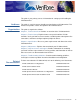
PREFACE This guide is your primary source of information for setting up and installing the VX 520 terminal. Audience Organization This guide is useful for anyone installing and configuring a VX 520 terminal. This manual also provides a basic description of the terminal features. This guide is organized as follows: Chapter 1, Terminal Overview. Provides an overview of the VX 520 terminals. Chapter 2, Terminal Setup. Explains how to set up and install the VX 520 terminals.
P REFACE Conventions and Acronyms Conventions and Acronyms This section describes the conventions and acronyms used in this guide. Document Various conventions are used to help you quickly identify special formatting. Conventions Table 1 describes these conventions and provides examples of their use. Table 1 Document Conventions Convention Blue Text in blue indicates terms that are cross-referenced. See Conventions and Acronyms. Italics Italic typeface indicates book titles or emphasis.
P REFACE Conventions and Acronyms Table 2 Acronym Definitions (continued) Acronym Definitions LED Light Emitting Diode MRA Merchandise Return Authorization MSAM Micromodule-Size Security Access Module PCI Payment Card Industry PED PIN-Entry Devices PIN Personal Identification Number RAM Random Access Memory RJ-11 Registered Jack 11 RJ-45 Registered Jack 45 RS-232 Recommended Standard 232 SAM Security Access Module VPN VeriFone Part Number VX 520 INSTALLATION GUIDE 7
P REFACE Conventions and Acronyms 8 VX 520 INSTALLATION GUIDE
CHAPTER 1 Terminal Overview Use this chapter to find out more about the features and benefits of VX 520 terminals. The VX 520 standard terminal comes with an internal thermal printer (ITP) while the VX 520 Sprocket terminal comes with a dot-matrix, sprocket-fed printer.
TERMINAL O VERVIEW VX 520 Terminal VX 520 Terminal This section provides a brief description of the VX 520 terminal: • The VX 520 is a high performance countertop terminal with enhanced communication options. • The VX 520 offers several communication options, enhanced display, increased processing power, expanded memory, and two USB peripheral ports. The VX 520 terminal uses a robust, sleek, and highly functional design. NOTE VeriFone ships variants of the VX 520 terminals for different markets.
TERMINAL O VERVIEW VX 520 Terminal VX 520 Features and VX 520 terminals provide the right combination of features and functions. This Benefits includes a triple-track magnetic-stripe card reader, landed smart card reader, integrated PIN pad, a quiet internal thermal printer (ITP). Connectivity • Host USB port • Client USB port • RJ-11 port • RS-232 port • Ethernet Port NOTE The connectivity ports are easily accessible from the underside of the terminal.
TERMINAL O VERVIEW VX 520 Terminal Exceptional Ease of Use • The bold design is sleek, stylish, and lightweight for conveniently handing the terminal to the consumer for PIN entry or other input. • An intuitive ATM-style interface, a large 8-line by 21-character backlit display with backlit keypad, and extra-size menu prompts, simplify training and reduce help desk calls. • The integrated printer simplifies paper loading and reduces paper jams.
TERMINAL O VERVIEW VX 520 Sprocket Terminal VX 520 Sprocket This section provides a brief description of the VX 520 Sprocket terminal: Terminal • An optional configuration of the VX 520 replaces the thermal printer with a sprocket printer, an additional telephone port (RJ-11) and power buttons. • The VX 520 Sprocket configuration enjoys the same communication and performance capabilities as the standard VX 520. The VX 520 Sprocket terminal uses a robust, highly functional design.
TERMINAL O VERVIEW VX 520 Sprocket Terminal Performance • 400 MHz Processor (CPU) • 160 MB total memory (128 MB Flash, 32 MB RAM) • 128/64 white backlit LCD • Fastest encryption/decryption appliance on the market Security • PCI PED 2.0 security Exceptional Ease of Use • Soft power buttons. Pressing the Enter key for at least three seconds powers terminal on, while pressing the Cancel key for at least four seconds powers the terminal off.
CHAPTER 2 Terminal Setup Use this chapter to set up and use your VX 520 terminal. Package contents and setup procedures may vary for different VX 520 models: The standard VX 520 uses thermal paper rolls while the VX 520 Sprocket uses carbonized paper sheets. Use the procedures in this section to set up and use your terminal.
TERMINAL S ETUP VX 520 Setup VX 520 Setup This section describes the setup procedures for the VX 520 terminal.
TERMINAL S ETUP VX 520 Setup Electrical Considerations • Avoid using this product during electrical storms. • Avoid locations near electrical appliances or other devices that cause excessive voltage fluctuations or emit electrical noise (for example, air conditioners, electric motors, neon signs, high-frequency or magnetic security devices, or computer equipment). • Do not use the terminal near water or in moist conditions.
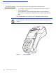
TERMINAL S ETUP VX 520 Setup Examining Terminal Before you continue the installation process, notice the features of the VX 520 Features terminal (see Figure 3).
TERMINAL S ETUP VX 520 Setup c Four unlabeled, programmable function keys above the keypad. d Three color-coded function keys below the keypad (icons at right; from left to right: CANCEL, BACKSPACE/CLEAR, ENTER). e An ALPHA key centered at the top of the keypad. A magnetic card reader, built into the right side. The icon at right shows the proper swipe direction, with the stripe down and facing inward, toward the keypad. • The VeriFone logo blue indicator LED indicates power is ON.
TERMINAL S ETUP VX 520 Setup Figure 5 and Figure 6 show the connection ports for the VX 520 terminal. POWER PORT RS-232 SERIAL PORT 23 RJ-11 TELEPHONE PORT %4( Figure 5 VX 520 Power and Connection Ports %4( HOST USB PORT ETHERNET PORT 23 CLIENT USB PORT Figure 6 WARNING 20 VX 520 INSTALLATION GUIDE Additional VX 520 Connection Ports Do not connect the terminal to the power supply until all the peripherals are attached.
TERMINAL S ETUP VX 520 Setup To use the The connection ports offer multiple connectivity for the VX 520 terminal. Please connection ports refer to the following list of peripheral devices for the connectivity options.
TERMINAL S ETUP VX 520 Setup Establishing Connect the telephone cord to the communication port on the terminal, then route Telephone Line it directly to a telephone wall jack (see Figure 7). This is a direct connection and Connections the line is dedicated to the terminal. RJ-11 23 ( %4 Figure 7 WARNING VX 520 Direct Telephone Connection To reduce the risk of fire, use only No. 26AWG or larger UL Listed or CSA Certified Telecommunication Line Cord.
TERMINAL S ETUP VX 520 Setup To install a paper roll 1 Hook your finger under the latch and lift up to swing the paper roll cover open (see Figure 8). Figure 8 Opening the Printer Cover 2 Remove any partial roll of paper in the printer tray by lifting it up. 3 Loosen the glued leading edge of the new paper roll or remove the protective strip. Unwind the paper roll past any glue residue. 4 Hold the roll so the paper feeds from the bottom of the roll. 5 Drop the paper roll into the printer tray.
TERMINAL S ETUP VX 520 Setup 7 Close the paper roll cover by gently pressing directly on the cover until it clicks shut, allowing a small amount of paper past the glue residue to extend outside the printer door. (see Figure 10). CAUTION To prevent the paper roll cover from damaging the print roller, always gently press down on the printer dust cover to close it. Figure 10 Closing Paper Roll Cover 8 Tear the paper off against the serrated metal strip in the printer.
TERMINAL S ETUP VX 520 Setup To install or replace 1 MSAMs Remove the power cord from the power outlet. 2 Place the terminal upside down on a soft, clean surface to protect the display from scratches. 3 Press the unlocking button and then lift the rear cover to access the MSAM cardholder panel. 23 %4( Figure 11 Opening VX 520 Rear Cover 4 Hold the MSAM cardholder panel, grasp firmly and pull upward to expose the MSAM slots.
TERMINAL S ETUP VX 520 Setup 5 Install an MSAM card by carefully sliding it into the slot until it is fully inserted. ( %4 23 Figure 13 NOTE Installing an MSAM Card Before inserting the MSAM card, position it as shown in Figure 13, with the card’s gold contacts facing down. The cardholder connector base has an image resembling the notched corner of an MSAM card to ensure the card is positioned correctly. 6 Close the MSAM cardholder panel, and then replace the terminal rear cover.
TERMINAL S ETUP VX 520 Setup Optional Device Connections The VX 520 terminal has a port that can operate either as a PIN pad port or an RS-232 port, depending on the power source available. Connecting the PIN Use the following procedures to connect a PIN pad or smart card reader. pad or Smart Card Reader to the VX 520 NOTE When the VX 520 terminal is powered via the corded power supply, the terminal provides 4.0 A at 9.3V DC. This power will drive most VeriFone accessories.
TERMINAL S ETUP VX 520 Setup Connecting ECRs to The VX 520 terminal also supports Electronic Cash Registers (ECR). Contact the VX 520 your VeriFone representative or visit the online store at www.store.verifone.com for information on these devices. Figure 15 provides an example of a peripheral connection to the USB port. CAUTION 23 %4 ( ECRs require a separate power source. Before connecting a check reader or similar device, remove the power cord and ensure that the indicator LED is not lit.
TERMINAL S ETUP VX 520 Setup Connecting the When you have finished connecting optional peripheral(s), you are ready to Terminal Power connect the VX 520 terminal to the provided power source. Pack CAUTION Using an incorrectly rated power supply may damage the terminal or cause it not to work as specified. Before troubleshooting, ensure that the power supply being used to power the terminal matches the requirements specified on the bottom of the terminal.
TERMINAL S ETUP VX 520 Setup VeriFone recommends connecting wall power in the following order: NOTE 1 Connect the terminal to the power supply. 2 Connect the power supply to the power cord. 3 Connect the power cord to the wall outlet. When the terminal has power, the terminal lights are activated and the LED indicator remains lit. If an application is loaded in the terminal, it starts after the initial VeriFone copyright screen and usually displays a unique copyright screen.
TERMINAL S ETUP VX 520 Setup 3 Remove the card only when the application indicates the transaction is complete. Figure 18 CAUTION Inserting a Smart Card Leave the smart card in the card reader until the transaction is complete. Premature card removal will invalidate the transaction. Using the Magnetic The VX 520 terminal supports credit or debit card transactions.
TERMINAL S ETUP VX 520 Sprocket Setup VX 520 Sprocket Setup This section describes the setup procedures for the VX 520 Sprocket terminal.
TERMINAL S ETUP VX 520 Sprocket Setup Electrical Considerations • Avoid using this product during electrical storms. • Avoid locations near electrical appliances or other devices that cause excessive voltage fluctuations or emit electrical noise (for example, air conditioners, electric motors, neon signs, high-frequency or magnetic security devices, or computer equipment). • Do not use the terminal near water or in moist conditions.
TERMINAL S ETUP VX 520 Sprocket Setup Examining Terminal Before you continue the installation process, notice the features of the VX 520 Features Sprocket terminal (see Figure 20).
TERMINAL S ETUP VX 520 Sprocket Setup d Three color-coded function keys below the keypad (icons at right; from left to right: CANCEL, BACKSPACE/CLEAR, ENTER). The Cancel key also acts as the Power Off button, while the Enter key also functions as the Power On button. Press the Enter key for at least three seconds to power on the terminal, and press the Cancel key for at least four seconds to power the terminal off e An ALPHA key centered at the top of the keypad.
TERMINAL S ETUP VX 520 Sprocket Setup Connection Ports Turn the terminal upside down to view the connection ports. Notice that the ports are recessed. Different ports provide connections to a communications line, optional peripheral devices, and the power supply. Figure 21 and Figure 22 show the connection ports for the VX 520 Sprocket terminal.
TERMINAL S ETUP VX 520 Sprocket Setup To use the The connection ports offer multiple connectivity for the VX 520 Sprocket terminal. connection ports Please refer to the following list of peripheral devices for the connectivity options.
TERMINAL S ETUP VX 520 Sprocket Setup Establishing Connect a telephone cord (RJ-11) from the Line port on the terminal, then route it Telephone and Line directly to a telephone wall jack. Connect a telephone unit to the Phone port (see Connections Figure 23). Figure 23 WARNING VX 520 Sprocket Telephone and Line Connections To reduce the risk of fire, use only No. 26AWG or larger UL Listed or CSA Certified Telecommunication Line Cord.
TERMINAL S ETUP VX 520 Sprocket Setup 3 Hook the clasps into the slots to secure the tray and snap the lock on the lower end of the tray.
TERMINAL S ETUP VX 520 Sprocket Setup Installing Paper in Before you can process transactions that require a receipt or record, you must the Tray install paper in the printer tray. The VX 520 Sprocket uses a stack of double-ply carbonized paper. To install a paper 1 stack Remove any partial stack of paper in the printer tray. 2 Place the new stack of paper into the tray 3 Feed the first sheet of paper into the sprocket printer and then turn the sprocket to feed the paper to the printer.
TERMINAL S ETUP VX 520 Sprocket Setup NOTE 5 Remove any previously installed MSAM card by sliding the card from the MSAM cardholder. 6 Install an MSAM card by carefully sliding it into the slot until it is fully inserted. Before inserting the MSAM card, position it as shown in Figure 26, with the card’s gold contacts facing down. The cardholder connector base has an image resembling the notched corner of an MSAM card to ensure the card is positioned correctly.
TERMINAL S ETUP VX 520 Sprocket Setup Connecting the PIN Use the following procedures to connect a PIN pad to the VX 520 Sprocket. pad or Smart Card Reader to the VX 520 Figure 27 provides an example of a peripheral connection to the Host USB port Sprocket RS232 ETH PHONE Figure 27 VX 520 Sprocket Sample PIN pad Connection 1 Turn the terminal upside down to access the connection ports. 2 Insert the USB connector of the PIN pad into the USB port of the VX 520 Sprocket.
TERMINAL S ETUP VX 520 Sprocket Setup Connecting the When you have finished connecting optional peripheral(s), you are ready to Terminal Power connect the VX 520 Sprocket terminal to the provided power source. Pack CAUTION Using an incorrectly rated power supply may damage the terminal or cause it not to work as specified. Before troubleshooting, ensure that the power supply being used to power the terminal matches the requirements specified on the bottom of the terminal.
TERMINAL S ETUP VX 520 Sprocket Setup 6 Plug the AC power cord into a wall outlet or powered surge protector. 7 Press the Enter key for at least three seconds to power on the terminal. WARNING Do not plug the power pack into an outdoor outlet or operate the terminal outdoors. Disconnecting the power during a transaction may cause transaction data files not yet stored in terminal memory to be lost.
TERMINAL S ETUP VX 520 Sprocket Setup Using the Smart The smart card transaction procedure may vary from one application to another. Card Reader Verify the procedure with your application provider before performing a smart card transaction. To conduct a smart 1 card transaction Position a smart card with the contacts facing upward (see Figure 30). 2 Insert the smart card into the smart card reader slot in a smooth, continuous motion until it seats firmly.
TERMINAL S ETUP VX 520 Sprocket Setup Using the Magnetic The VX 520 Sprocket terminal supports credit or debit card transactions. Card Reader To conduct a credit or 1 debit card transaction Position a magnetic card with the stripe in the card reader and facing inward, toward the keypad. 2 To ensure a proper read of the magnetic swipe card, the user should insert the magnetic card from the top of the unit, as shown in Figure 31. 3 Swipe the card through the magnetic card reader.
CHAPTER 3 Specifications This chapter discusses power requirements, dimensions, and other specifications of the VX 520 terminals: • VX 520 Specifications • VX 520 Sprocket Specifications VX 520 INSTALLATION GUIDE 47
S PECIFICATIONS VX 520 Specifications VX 520 Specifications Power VX 520 terminal: 9.3V DC; 4.0 A DC Power Pack UL, ITE listed, LPS power supply: a Input rated: 100 - 240V AC, 50/60 Hz b Output rated: 9.3V DC 4.0 A Barrel connector polarity: – Temperature • Operating temperature: 0° to 40° C (32° to 104° F) • Storage temperature: -20° to + 60° C (-4° to 140° F) • Relative humidity: 5% to 85%; no condensation External • Dimensions • 48 + VX 520 INSTALLATION GUIDE Length: 203 mm (7.
S PECIFICATIONS VX 520 Sprocket Specifications VX 520 Sprocket Specifications Power VX 520 Sprocket terminal: 24V DC; 1.7 A DC Power Pack UL, ITE listed, LPS power supply: a Input rated: 100 - 240V AC, 50/60 Hz b Output rated: 24V DC; 1.7 A Barrel connector polarity: – Temperature • + Operating temperature: 0° to 40° C (32° to 104° F) • Storage temperature: -20° to + 60° C (-4° to 140° F) • Relative humidity: 5% to 85%; no condensation External • Dimensions • Length: 263.48 mm (10.
S PECIFICATIONS VX 520 Sprocket Specifications 50 VX 520 INSTALLATION GUIDE
CHAPTER 4 Maintenance The VX 520 terminal has no user-maintainable parts. Clean the Terminal To clean the terminal, use a clean cloth slightly dampened with water and a drop or two of mild soap. For stubborn stains, use alcohol or an alcohol-based cleaner. CAUTION Never use thinner, trichloroethylene, or ketone-based solvents – they may cause deterioration of plastic or rubber parts. Do not spray cleaners or other solutions directly onto the keypad or terminal display.
M AINTENANCE Smart Card Reader 52 VX 520 INSTALLATION GUIDE
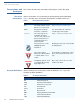
CHAPTER 5 VeriFone Service and Support For terminal problems, contact your local VeriFone representative or service provider. For product service and repair information: Return a Terminal for Service NOTE • USA – VeriFone Service and Support Group, 1-800-VeriFone (837-4366), Monday - Friday, 8 A.M. - 8 P.M., Eastern time • International – Contact your VeriFone representative Before returning a VX 520 terminal to VeriFone, you must obtain an MRA number.
VERI F ONE S ERVICE AND S UPPORT Accessories and Documentation c Complete the Inquiry Contact Form at http://www.verifone.com/aboutus/contact/contact_form.cfm. NOTE • Address the Subject box with to “VeriFone MRA Dept.” • Reference the model and part number in the Note box. One MRA number must be issued for each VX 520 terminal you return to VeriFone, even if you are returning several of the same model. 3 Describe the problem(s).
VERI F ONE S ERVICE AND S UPPORT Accessories and Documentation VeriFone Cleaning Kit VPN 02746-01 Cleaning kit Telephone Line Cord VPN CBL000-001-01-A 2.
VERI F ONE S ERVICE AND S UPPORT Accessories and Documentation 56 VX 520 INSTALLATION GUIDE
CHAPTER 6 Troubleshooting Guidelines The troubleshooting guidelines provided in the following section are included to assist you to successfully install and configure your VX 520 terminal. If you have problems operating your VX 520 terminal, please read through these troubleshooting examples. If the problem persists even after performing the outlined guidelines or if the problem is not described below, contact your local VeriFone representative for assistance.
TROUBLESHOOTING G UIDELINES Terminal Does Not Dial Out Terminal Does If the terminal does not dial out: Not Dial Out • Check the telephone line connections. • Check that the telephone line is working by plugging it into a working telephone and listening for a dial tone. • Replace the telephone cable that connects the terminal with a cable you know is working correctly. • If the problem persists, contact your local VeriFone service provider.
TROUBLESHOOTING G UIDELINES Transactions Fail To Process Transactions Fail To Process There are several reasons why the terminal may not be processing transactions. Use the following steps to troubleshoot failures. Check the Magnetic Card Reader • Perform a test transaction using one or more different magnetic stripe cards to ensure the problem is not a defective card. • Ensure that you are swiping cards properly.
TROUBLESHOOTING G UIDELINES Printer Does Not Print Printer Does Not If the printer does not work properly: Print • Check terminal power connection. • Check if the printer is out of paper and that the roll is properly installed. Open the paper roll cover and install a new roll of printer paper or ensure that the roll is feeding from the bottom. • Verify that the printer roller and paper roll dust cover are properly installed.
INDEX A accessories 54 documentation 55 ordering 55 power packs 54 printer paper 54 telephone line cord 55 VeriFone cleaning kit 55 C cleaning kit 55 connection ports VX 520 19 VX 520 Sprocket 36 contact VeriFone 53 D dial out problems troubleshooting 58 displays troubleshooting 57, 60 documentation 54 acronym definitions 6 conventions 6 ordering 55 E electrical considerations 17, 24, 33 electrostatic discharges 24 prevention 24 environmental factors 16 I installation connecting a PIN pad to VX 520 27 c
I NDEX S troubleshooting 58 peripheral devices troubleshooting 58 peripherals troubleshooting 58 power buttons 14, 35 power packs AC version 54 connecting 29, 42 DC version 54 ordering 54 printer paper 40 mm thermal 54 49 mm thermal 54 sprocket-fed, carbonized 54 printer paper VX 520 storage 22 printers troubleshooting 60 privacy shield VX 520 30 VX 520 Sprocket 43 VX 520 Sprocket general 34 terminals accessories 54 cleaning 51 documentation 54 environmental factors 16 repair 53 replacement 53 troubleshoo
I NDEX V VX 520 INSTALLATION GUIDE 63
VeriFone, Inc. 2099 Gateway Place, Suite 600 San Jose, CA, 95110 USA Tel: (800) VeriFone (837-4366) www.verifone.