
User's Manual


Table Of Contents
- VX 520 Installation Guide
- Contents
- Preface
- Terminal Overview
- Terminal Setup
- VX 520 Setup
- Selecting Terminal Location
- Unpacking the Shipping Carton
- Examining Terminal Features
- Installing the Smart Battery (VX 520 GPRS Only)
- Establishing Telephone Line Connections
- Installing a Paper Roll in the Printer
- Installing/Replacing MSAM Cards
- Installing/Replacing SIM Card (VX 520 GPRS Only)
- Connecting Optional Devices
- Connecting the Terminal Power Pack
- Charging the Smart Battery (VX 520 GPRS Only)
- Privacy Shield (Optional)
- Using the Smart Card Reader
- Using the Magnetic Card Reader
- VX 520 Sprocket Setup
- Selecting Terminal Location
- Unpacking the Shipping Carton
- Examining Terminal Features
- Establishing Telephone and Line Connections
- Installing Paper Tray
- Installing Paper in the Tray
- Installing/Replacing MSAM Cards
- Connecting Optional Devices
- Connecting the Terminal Power Pack
- Privacy Shield (Optional)
- Using the Smart Card Reader
- Using the Magnetic Card Reader
- VX 520 Setup
- Specifications
- Maintenance
- Troubleshooting Guidelines
- VeriFone Service and Support
- Contact VeriFone
TERMINAL SETUP
VX 520 Setup
VX 520 I
NSTALLATION GUIDE 33
V
E
R
I
F
O N
E
C
O
N
F I
DE
N
T
I
A
L
TE
MP
LATE
R
EV
F
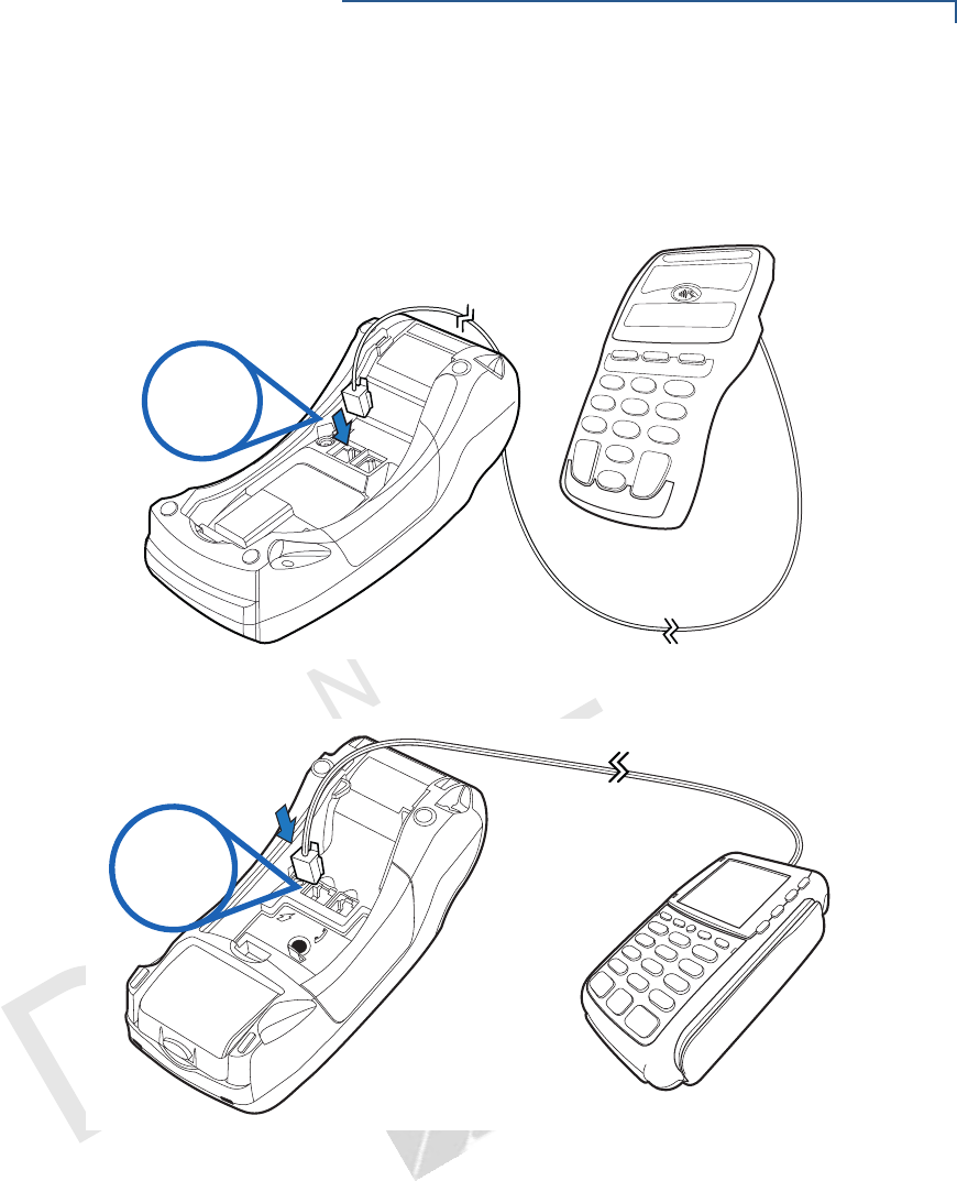
3 Insert the larger RJ-45-type connector on the other end of the PIN pad cable
into the PIN pad serial port on the terminal. Figure 25 provides an example of
a smart card reader and PIN pad connection to the PIN pad serial port.
Figure 25 VX 520 D/E Sample PIN Pad Connection
Figure 26 VX 520 GPRS Sample PIN Pad Connection
RS-232
23
RS-232