
User's Manual


Table Of Contents
- VX 520 Installation Guide
- Contents
- Preface
- Terminal Overview
- Terminal Setup
- VX 520 Setup
- Selecting Terminal Location
- Unpacking the Shipping Carton
- Examining Terminal Features
- Installing the Smart Battery (VX 520 GPRS Only)
- Establishing Telephone Line Connections
- Installing a Paper Roll in the Printer
- Installing/Replacing MSAM Cards
- Installing/Replacing SIM Card (VX 520 GPRS Only)
- Connecting Optional Devices
- Connecting the Terminal Power Pack
- Charging the Smart Battery (VX 520 GPRS Only)
- Privacy Shield (Optional)
- Using the Smart Card Reader
- Using the Magnetic Card Reader
- VX 520 Sprocket Setup
- Selecting Terminal Location
- Unpacking the Shipping Carton
- Examining Terminal Features
- Establishing Telephone and Line Connections
- Installing Paper Tray
- Installing Paper in the Tray
- Installing/Replacing MSAM Cards
- Connecting Optional Devices
- Connecting the Terminal Power Pack
- Privacy Shield (Optional)
- Using the Smart Card Reader
- Using the Magnetic Card Reader
- VX 520 Setup
- Specifications
- Maintenance
- Troubleshooting Guidelines
- VeriFone Service and Support
- Contact VeriFone
TERMINAL SETUP
VX 520 Sprocket Setup
VX 520 I
NSTALLATION GUIDE 45
V
E
R
I
F
O N
E
C
O
N
F I
DE
N
T
I
A
L
TE
MP
LATE
R
EV
F
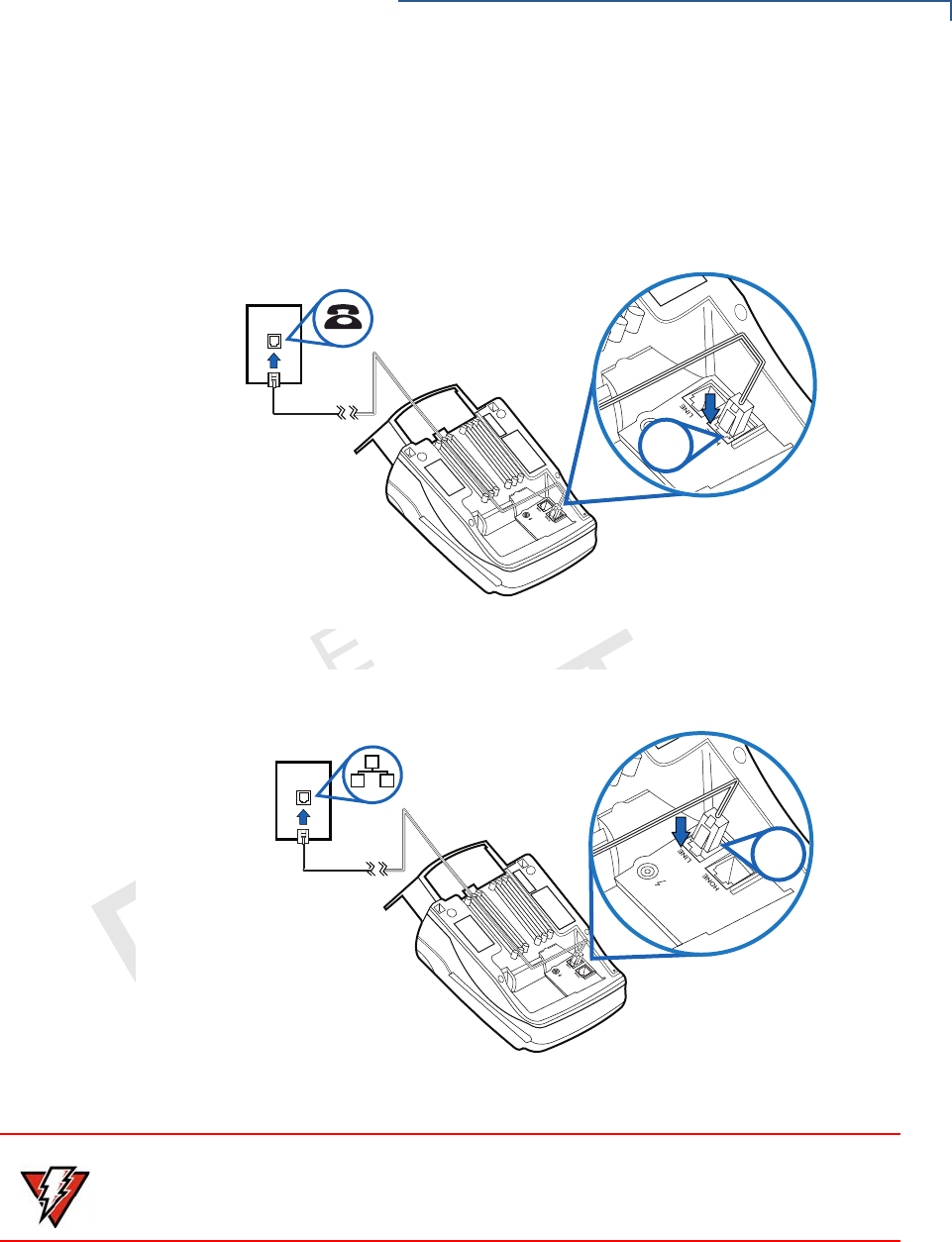
Establishing
Telephone and Line
Connections
Connect the telephone cord to the communication port on the terminal, then route
it directly to a telephone wall jack. Connect the telephone to the phone port
(see Figure 37 and Figure 38). The communications connection is dedicated to
the terminal.
Figure 37 VX 520 Sprocket Telephone Connection
Figure 38 VX 520 Sprocket Line Connection
RJ11
RJ11
WARNING
To reduce the risk of fire, use only No. 26AWG or larger UL Listed or CSA
Certified Telecommunication Line Cord.