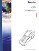
Vx670 Installation Guide VeriFone Part Number 24003, Revision A.
Vx670 Installation Guide © 2006 VeriFone, Inc. All rights reserved. No part of the contents of this document may be reproduced or transmitted in any form without the written permission of VeriFone, Inc. The information contained in this document is subject to change without notice. Although VeriFone has attempted to ensure the accuracy of the contents of this document, this document may include errors or omissions.
CONTENTS PREFACE . . . . . . . . . . . . . . . . . . . . . . . . . . . . . . . . . . . . . . . 5 Audience. . . . . . . . . . . . . . . . . . . . . . . . . . . . . . . . . . . . . . . . . . . . . . . . . . . . . . . . Organization . . . . . . . . . . . . . . . . . . . . . . . . . . . . . . . . . . . . . . . . . . . . . . . . . . . . . Related Documentation . . . . . . . . . . . . . . . . . . . . . . . . . . . . . . . . . . . . . . . . . . . . Conventions and Acronyms . . . . . . . . . . . . . . . . . . . . .
C ONTENTS Full-featured Base Station . . . . . . . . . . . . . . . . . . . . . . . . . . . . . . . . . . . . . . Powering up the Base Station. . . . . . . . . . . . . . . . . . . . . . . . . . . . . . . . . . . . Placing the Vx670 Terminal Onto the Base Station . . . . . . . . . . . . . . . . . . . . . . Attaching the USB Dongles to the Base Station. . . . . . . . . . . . . . . . . . . . . . . . . Charging the Spare Battery on the Base Station . . . . . . . . . . . . . . . . . . . . . . . .
PREFACE This guide is your primary source of information for setting up and installing the Vx670 terminal. Audience Organization This guide is useful for anyone installing and configuring a Vx670 terminal. Basic descriptions of the terminal features are also provided. This guide is organized as follows: Chapter 1, Terminal Overview. Provides an overview of the Vx670 terminal. Chapter 2, Terminal Setup. Explains how to set up and install the Vx670 terminal.
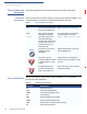
P REFACE Conventions and Acronyms Conventions and Acronyms This section describes the conventions and acronyms used in this guide. Document Various conventions are used to help you quickly identify special formatting. Table Conventions 1 describes these conventions and provides examples of their use. Table 1 Document Conventions Convention Meaning Example Blue Text in blue indicates terms that are cross referenced. See Conventions and Acronyms.
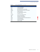
P REFACE Conventions and Acronyms Table 2 Acronym Definitions (continued) Acronym Definitions LCD Liquid Crystal Display LED Light Emitting Diode MRA Merchandise Return Authorization MSAM Micromodule-Size Security Access Module PED PIN-Entry Devices PIN Personal Identification Number RJ45 Registered Jack 45 RS-232 Recommended Standard 232 SAM Security Access Module SIM Subscriber Identity Module UART Universal Asynchronous Transmitter/Receiver USB Universal Serial Bus VPN VeriF
P REFACE Conventions and Acronyms 8 VX670 INSTALLATION GUIDE
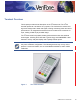
CHAPTER 1 Terminal Overview This chapter provides a brief description of the Vx670 terminal. The Vx670 terminal represents a revolution for e-payment. The Vx670 device uses a bold ergonomic design that is sleek and stylish, offering countertop power and 32-bit performance in an integrated terminal that can be handed to the consumer for input, making it ideal for pay-at-table usage. The Vx670 terminal is a portable, battery-powered device that uses wireless technologies, including Wi-Fi with 802.
TERMINAL O VERVIEW Features and Benefits Features at a glance • 32-bit ARM9 processor delivers power and usability in a convenient “hand-over” design. • Multi-application operating environment. • 32-bit processing and multi-tasking capabilities. • USB support for VeriFone peripheral devices. • Offers unsurpassed performance on EMV smart card transactions. • Security architecture meets specifications for PCI-PED and sophisticated file authentication.
TERMINAL O VERVIEW Features and Benefits • Sealed MSR blade locks out moisture for excellent spill resistance. • Innovative design resists spills by forcing liquid down and off the front of the terminal • Integrated PINpad offers added convenience to handle PIN-based applications. • Uncompromising reliability from VeriFone, the worldwide leader in e-payment. • Complies with RoHS (Restriction of Hazardous Substances) directive of the European Union.
TERMINAL O VERVIEW Features and Benefits 12 VX670 INSTALLATION GUIDE
CHAPTER 2 Terminal Setup This chapter describes the terminal setup procedure. You will learn about: Selecting Terminal Location • Selecting Terminal Location. • Unpacking the Shipping Carton. • Examining Terminal Features. • Examining the Handy-Link Connector. • Establishing Telephone Line Connections. • Installing the Paper Roll. • Installing/Replacing MSAM Cards. • Installing/Replacing SIM Card (GSM/GPRS Models). • Install the battery (see Figure 16)..
TERMINAL S ETUP Unpacking the Shipping Carton • Environmental • Factors CAUTION Do not use the terminal where there is high heat, dust, humidity, moisture, or caustic chemicals or oils. • Keep the terminal away from direct sunlight and anything that radiates heat, such as a stove or motor. • Do not use the terminal outdoors. The terminal is not waterproof or dustproof, and is intended for indoor use only. Any damage to the unit from exposure to rain or dust may void any warranty.
TERMINAL S ETUP Examining Terminal Features Examining Terminal Features Before you continue the installation process, notice the features of the Vx670 terminal (see Figure 2).
TERMINAL S ETUP Examining Terminal Features • A magnetic card reader, built into the right side. Swipe the card using the proper direction, with the stripe down and facing inward, toward the keypad. • A green indicator LED indicates power is ON. • An internal thermal printer at the back of the terminal. • A smart card reader, built into the front of the terminal. For directions on how to use a smart card, see Conducting Smart Card Transactions.
TERMINAL S ETUP Examining the Handy-Link Connector Examining the Handy-Link Connector The Handy-Link connector is a cell phone style connector that supports a wide variety of communication ports via cable adapters. CELL PHONE STYLE CONNECTOR USB HOST SERIAL PORT (COM 1) USB DEVICE Figure 3 The Vx670 Handy-Link Connector Cable Adapters The cable adapters enable the Vx670 terminal to connect to .....
TERMINAL S ETUP Examining the Handy-Link Connector USB Host A 2-Wire USB Host port for external peripherals. A connector adaptor provides for standard USB host connection. USB Device A 2-Wire USB device port connected directly to the PC’s USB ports. This port is mainly for debugging purposes. NOTE A Base Station may be provided with the Vx670 terminal. A full-feature Base Station has two USB host ports for external dongles as well as a battery charger slot for charging an extra lithium-ion battery pack.
TERMINAL S ETUP Establishing Telephone Line Connections USB Dongle – Modem A modem in the form of a USB dongle is provided with the Vx670 terminal. The USB Dongle – Modem provides communication via a telephone line at speeds of up to 14,400 bps. The USB Dongle – Modem can also be connected to the fullfeature Base Station when the terminal is in the station. USB Dongle – Serial The USB Dongle – Serial provides the Vx670 terminal with a serial communication port for backward compatibility.
TERMINAL S ETUP Installing the Paper Roll Installing the Paper Roll A fast, quiet thermal printer is built into the Vx670 terminal. Before you can process transactions that require a receipt or record, you must install a roll of thermal-sensitive paper in the printer. The ITP uses a roll of single-ply, thermal-sensitive paper 57 millimeters (2.24 inches) wide and 25 meters (82 feet) long.
TERMINAL S ETUP Installing the Paper Roll 2 Lift the printer cover up and back. Figure 7 Opening the Printer Cover 3 Remove any partial roll of paper in the printer tray by lifting it up (see Figure 8). 4 Loosen the glued leading edge of the paper or remove the protective strip from the new roll of paper. Unwind the paper roll past any glue residue. Figure 8 Removing Partial Paper Roll 5 Hold the roll so the paper feeds from the bottom of the roll (see Figure 10).
TERMINAL S ETUP Installing the Paper Roll 6 Drop the paper roll into the printer tray. Figure 9 Loading Paper Roll 7 Pull paper up past the glue residue from the printer tray. 8 Close the paper roll cover by gently pressing directly on the cover until it clicks shut, allowing a small amount of paper past the glue residue to extend outside the printer door. CAUTION To prevent damaging the print roller, always gently press down on the paper roll cover to close it.
TERMINAL S ETUP Installing/Replacing MSAM Cards 9 Tear the paper off against the serrated plastic strip in the printer. Installing/ Replacing MSAM Cards When you first receive your Vx670 terminal, you may need to install one or more MSAM cards or you may need to replace old cards. CAUTION Observe standard precautions when handling electrostatically sensitive devices. Electrostatic discharges can damage this equipment. VeriFone recommends using a grounded anti-static wrist strap.
TERMINAL S ETUP Installing/Replacing SIM Card (GSM/GPRS Models) 5 Install an MSAM card by aligning the card and carefully sliding it within the guides on the cover until it is fully inserted (see Figure 12). The MSAM card holders are labeled MSAM1, MSAM2, and MSAM3. Figure 12 NOTE Installing MSAM Card Before inserting the MSAM card, position it as shown in Figure 12, with the card’s gold contacts facing the smart card reader end of the terminal.
TERMINAL S ETUP Connecting the Terminal Power Pack 4 Insert the SIM into the cardholder. NOTE There is only one SIM slot, but there are multiple SAM slots. Make sure you insert the SIM card into the SIM slot, as shown in Figure 14. Figure 14 Inserting SIM Card 5 Install the battery (see Figure 16). Connecting the Terminal Power Pack CAUTION When you have finished connecting optional peripheral(s), you are ready to connect the Vx670 terminal to the provided power source.
TERMINAL S ETUP Using the Smart Battery To Connect the 1 Terminal Power Pack Insert the round barrel connector into the power port in the Handy-Link connector, as shown in Figure 15. Figure 15 Vx670 Power Pack Connection 2 Insert the AC power cord into the power pack. 3 Plug the AC power cord into a wall outlet or powered surge protector. WARNING Do not plug the power pack into an outdoor outlet or operate the terminal outdoors.
TERMINAL S ETUP V x 670 Battery Behavior (No Power Cord) Standard Battery Pack The standard battery has a capacity of 1250mAh. It is suited for WiFi and pay-attable applications where frequent charging is required. High-Capacity Battery Pack The high-capacity battery pack is larger than the standard battery pack and is more suitable for GPRS/CDMA applications.
TERMINAL S ETUP Installing the Smart Battery When the terminal has power, the terminal lights are activated and the green LED indicator remains lit. NOTE If an application is loaded in the terminal, it starts after the initial VeriFone copyright screen and usually displays a unique copyright screen. If no application is loaded in the terminal, DOWNLOAD NEEDED appears on screen after the initial VeriFone copyright screen.
TERMINAL S ETUP Charging the Smart Battery Removal To remove the Vx670 smart battery, press the locking tab and pull the smart battery from its slot. Figure 17 Charging the Smart Battery Detaching the Smart Battery from the Vx670 Terminal After unpacking your Vx670 terminal, install the battery and connect the power pack to the unit for 6 hours. It is also recommended that the smart battery receive a periodic full discharge. To ensure a full discharge, use the unit until the battery is fully drained.
TERMINAL S ETUP Using the V x 670 Base Station Using the Vx670 Base Station The primary purpose of the Base Station is to charge the terminal battery and provide a docking station for the terminal after being used in pay-at-table environments. The Base Station can be positioned on a countertop or mounted to the wall. There are two types of Base Station, the standard model and the full-featured model. Standard Base The standard Base Station can charge the Vx670 terminal.
TERMINAL S ETUP Using the V x 670 Base Station For more information on charging the spare battery on the Full-Featured Base Station and connecting external dongles to the USB ports, see Charging the Spare Battery on the Base Station and Attaching the USB Dongles to the Base Station. Powering up the Use the procedure in this section to connect the Vx670 Base Station to a power Base Station source. 1 Insert the round barrel connector of the power pack into the power port at the back of the Base Station.
TERMINAL S ETUP Placing the V x 670 Terminal Onto the Base Station Placing the x V 670 Terminal Onto the Base Station NOTE The Vx670 terminal can be placed on the Base Station when not in use or to charge the battery. External peripherals can also be attached to the terminal via USB dongles while it is on the Base Station (see Attaching the USB Dongles to the Base Station).
TERMINAL S ETUP Charging the Spare Battery on the Base Station 1 Insert the USB dongle into the USB port located at the back of the Base Station. Figure 20 Insert External Dongle Into USB Port 2 After inserting the external dongle into the USB port, place the Vx670 terminal onto the Base Station (see Powering up the Base Station). 3 Connect the peripheral to the external dongle.
TERMINAL S ETUP Conducting Wireless Transactions 3 Place the Vx670 terminal onto the Base Station to charge both the spare and installed battery packs at the same time. Conducting To conduct a wireless transaction: Wireless • Ensure the terminal is in an optimal position for transmitting. Transactions • Conducting Smart Card Transactions Follow the on-screen instructions provided with your application. The smart card transaction procedure may vary from one application to another.
TERMINAL S ETUP Using the Magnetic Card Reader 3 Remove the card only when the application indicates the transaction is complete. Figure 22 CAUTION Using the Magnetic Card Reader Inserting a Smart Card Leave the smart card in the card reader until the transaction is complete. Premature card removal will invalidate the transaction. The Vx670 terminal supports credit/debit card transactions.
TERMINAL S ETUP Using the Magnetic Card Reader 3 Swipe the card through the magnetic card reader.
CHAPTER 3 Specifications This chapter discusses power requirements, dimensions, and other specifications of the Vx670 terminal. Power DC Power Pack Vx670 terminal: 9 V DC; 4.0 A UL, ITE listed, Class 2 power supply: a Input rated: 100 - 240V AC, 50/60 Hz b Output rated: 8.6 - 9.4V DC 4.
S PECIFICATIONS V x 670 External Dimensions 38 VX670 INSTALLATION GUIDE
CHAPTER 4 Maintenance The Vx670 terminal and base stations have no user-maintainable parts. Cleaning the Terminal To clean the terminal and base station, use a clean cloth slightly dampened with water and a drop or two of mild soap. For stubborn stains, use alcohol or an alcohol-based cleaner. CAUTION Never use thinner, trichloroethylene, or ketone-based solvents – they may cause deterioration of plastic or rubber parts.
M AINTENANCE Smart Card Reader 40 VX670 INSTALLATION GUIDE
CHAPTER 5 VeriFone Service and Support For Vx670 terminal problems, contact your local VeriFone representative or service provider. For Vx670 product service and repair information: Returning a Terminal or Smart Battery for Service NOTE • USA – VeriFone Service and Support Group, 1-800-VeriFone (837-4366), Monday - Friday, 8 A.M. - 8 P.M.
VERI F ONE S ERVICE AND S UPPORT Accessories and Documentation c Complete the Inquiry Contact Form at http://www.verifone.com/aboutus/ contact/contact_form.cfm. NOTE • Address the Subject box with to “VeriFone MRA Dept.” • Reference the model and part number in the Note box. One MRA number must be issued for each Vx670 terminal you return to VeriFone, even if you are returning several of the same model. 3 Describe the problem(s).
VERI F ONE S ERVICE AND S UPPORT Accessories and Documentation VeriFone Cleaning Kit 02746-01 Cleaning Kit Telephone Line Cord 00124-17 2.
VERI F ONE S ERVICE AND S UPPORT Accessories and Documentation 44 VX670 INSTALLATION GUIDE
CHAPTER 6 Troubleshooting Guidelines The troubleshooting guidelines provided in the following section are included to assist you to successfully install and configure your Vx670 terminal. If you have problems operating your Vx670 terminal, please read through these troubleshooting examples. If the problem persists even after performing the outlined guidelines or if the problem is not described below, contact your local VeriFone representative for assistance.
TROUBLESHOOTING G UIDELINES Smart Battery Will Not Charge Smart Battery Will Not Charge NOTE The Vx670 smart battery must initially receive a full charge to calibrate its full charge capacity. Allow the Vx670 terminal to remain connected to the power pack for 6 hours to ensure the battery receives a full charge. Conserve battery power by turning the Vx670 terminal off when not in use.
TROUBLESHOOTING G UIDELINES Printer Paper Jam • Verify that the printer roller and paper roll dust cover are properly installed. • If the problem persists, contact your VeriFone distributor or service provider. Printer Paper If paper jams inside the printer: Jam • Press the button on the side of the terminal to unlatch the paper roll cover, then open the cover. WARNING • Remove the damaged paper from the paper roll and clear the feed mechanism.
TROUBLESHOOTING G UIDELINES Transactions Fail To Process • Ensure that you are swiping cards properly. With the Vx670 card reader, the black magnetic stripe on the card should face down and inward, toward the keypad and must be inserted from the top of the terminal (see Figure 23). • Process a transaction manually, using the keypad instead of the card reader. If the manual transaction works, the problem may be a defective card reader. • Contact your VeriFone distributor or service provider.
INDEX A environmental factors 14 accessories 42 documentation 43 ordering 43 power packs 42 telephone line cord 43 thermal printer paper 42 VeriFone cleaning kit 43 F B installation 9 connecting the terminal power pack 25 connecting the terminal to a telephone line 19 MSAM cardholders 23 MSAM cards 23 terminal location 13 unpacking the shipping carton 14 Base Station 30 batteries extending the battery life 29 See also smart battery battery mode Vx670 27 C cable adapters 17 cleaning kit 43 connection
I NDEX S DC version 42 ordering 42 printer paper ordering 42 printers troubleshooting 46 S service returning a battery for repair or replacement 41 returning a terminal for repair or replacement 41 SIM cards for GSM models 24 smart battery 29 battery life 29 charging 29 conserving power 27 disposal 29 features 27 installation 28 recharging 29 removal 29 troubleshooting 46 spare batteries charging on the Full-Featured Base Station 33 specifications DC power pack 37 power 37 temperature 37 Standard Base Sta
I NDEX W wireless transactions 34 VX670 INSTALLATION GUIDE 51
VeriFone, Inc. 2099 Gateway Place, Suite 600 San Jose, CA, 95110 USA Tel: (800) VeriFone (837-4366) www.verifone.com Vx670 Installation Guide VeriFone Part Number 24003, Revision A.