
Installation Guide
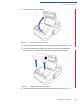
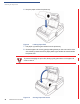
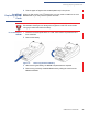
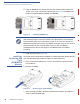
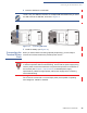
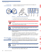
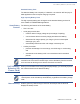
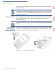
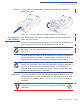
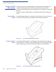
Table Of Contents
- Vx670
- Contents
- Preface
- Terminal Overview
- Terminal Setup
- Selecting Terminal Location
- Unpacking the Shipping Carton
- Examining Terminal Features
- Examining the Handy-Link Connector
- Establishing Telephone Line Connections
- Installing the Paper Roll
- Installing/ Replacing MSAM Cards
- Installing/ Replacing SIM Card (GSM/GPRS Models)
- Connecting the Terminal Power Pack
- Using the Smart Battery
- Vx670 Battery Behavior (No Power Cord)
- Installing the Smart Battery
- Charging the Smart Battery
- Using the Vx670 Base Station
- Placing the Vx670 Terminal Onto the Base Station
- Attaching the USB Dongles to the Base Station
- Charging the Spare Battery on the Base Station
- Conducting Wireless Transactions
- Conducting Smart Card Transactions
- Using the Magnetic Card Reader
- Specifications
- Maintenance
- VeriFone Service and Support
- Troubleshooting Guidelines
- Terminal Does Not Start
- Terminal Display Does not Show Correct/Readable Info
- Smart Battery Will Not Charge
- Spare Battery in Base Station Will Not Charge
- Blank Display
- Terminal Does Not Dial Out
- Printer Does Not Print
- Printer Paper Jam
- Peripheral Device Does Not Work
- Keypad Does Not Respond
- Transactions Fail To Process
- Index
- Contact VeriFone

TERMINAL SETUP
Installing/Replacing SIM Card (GSM/GPRS Models)
24 V
X
670 INSTALLATION GUIDE
5 Install an MSAM card by aligning the card and carefully sliding it within the
guides on the cover until it is fully inserted (see Figure 12). The MSAM card
holders are labeled MSAM1, MSAM2, and MSAM3.
Figure 12 Installing MSAM Card
6 Install the battery (see Figure 16).
Installing/
Replacing SIM
Card
(GSM/GPRS
Models)
The V
x
670 terminal supports the installation of a SIM (Subscriber Identity Module)
card. Use the following procedure to replace or install a SIM card.
1 Place the terminal upside down on a soft, clean surface to protect the lens
from scratches.
2 Remove the battery.
Figure 13 Removing the Smart Battery
3 After removing the battery, the SIM compartment is exposed. The SIM card
holder is labeled RADIO SIM.
NOTE
Before inserting the MSAM card, position it as shown in Figure 12, with the card’s
gold contacts facing the smart card reader end of the terminal. The cardholder
connector base has a set of contacts and a notch on one corner to ensure the
MSAM card is positioned correctly. The MSAM card has a notch on one corner to
ensure that it fits into the connector base in only one way. The MSAM
compartment door will not close properly if the MSAM cards are installed
incorrectly.