VX 680 Installation Guide R E S I V 68 4 . C N O I 4= *+, 356 ¶´ $%& -./ 78 9 63 '() 012 :;< VeriFone Part Number DOC268-003-EN-C, Revision C.
VX 680 Installation Guide © 2011 VeriFone, Inc. All rights reserved. No part of the contents of this document may be reproduced or transmitted in any form without the written permission of VeriFone, Inc. The information contained in this document is subject to change without notice. Although VeriFone has attempted to ensure the accuracy of the contents of this document, this document may include errors or omissions.
CONTENTS PREFACE . . . . . . . . . . . . . . . . . . . . . . . . . . . . . . . . . . . . . . . 7 Audience. . . . . . . . . . . . . . . . . . . . . . . . . . . . . . . . . . . . . . . . . . . . . . . . . . . . . . . . Organization . . . . . . . . . . . . . . . . . . . . . . . . . . . . . . . . . . . . . . . . . . . . . . . . . . . . . Related Documentation . . . . . . . . . . . . . . . . . . . . . . . . . . . . . . . . . . . . . . . . . . . . Conventions and Acronyms . . . . . . . . . . . . . . . . . . . . .
C ONTENTS Manual Shutdown . . . . . . . . . . . . . . . . . . . . . . . . . . . . . . . . . . . . . . . . . . . . . Installing the Smart Battery . . . . . . . . . . . . . . . . . . . . . . . . . . . . . . . . . . . . . . . . Removing the Smart Battery . . . . . . . . . . . . . . . . . . . . . . . . . . . . . . . . . . . . . . . Connecting the Terminal Power Pack . . . . . . . . . . . . . . . . . . . . . . . . . . . . . . . . Charging the Smart Battery . . . . . . . . . . . . . . . . . . . . . . . . . . . .
C ONTENTS CHAPTER 6 Troubleshooting Terminal Does Not Start . . . . . . . . . . . . . . . . . . . . . . . . . . . . . . . . . . . . . . . . . . . 57 Guidelines Terminal Display Does Not Show Correct/Readable Info. . . . . . . . . . . . . . . . . . 57 Smart Battery Does Not Charge. . . . . . . . . . . . . . . . . . . . . . . . . . . . . . . . . . . . . Spare Battery in Base Station Does Not Charge . . . . . . . . . . . . . . . . . . . . . . . . Blank Display . . . . . . . . . . . . . . . . . . . . . . . . .
C ONTENTS 6 VX 680 INSTALLATION GUIDE
PREFACE This guide is your primary source of information for setting up and installing the VX 680 terminal. Audience Organization This guide is useful for anyone installing and configuring a VX 680 terminal. Basic descriptions of the terminal features are also provided. This guide is organized as follows: Chapter 1, Terminal Overview. Provides an overview of the VX 680 terminal. Chapter 2, Terminal Setup. Explains how to set up and install the VX 680 terminal.
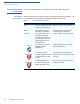
P REFACE Conventions and Acronyms Conventions and Acronyms This section describes the conventions and acronyms used in this guide. Document Various conventions are used to help you quickly identify special formatting. Table Conventions 1 describes these conventions and provides examples of their use. Table 1 Convention Meaning Example Blue Text in blue indicates terms that are cross referenced. See Conventions and Acronyms. Italics Italic typeface indicates book titles or emphasis.
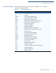
P REFACE Conventions and Acronyms Acronym Definitions Various acronyms are used in place of the full definition. Table 2 presents acronyms and their definitions.
P REFACE Conventions and Acronyms 10 VX 680 INSTALLATION GUIDE
CHAPTER 1 Terminal Overview This chapter provides a brief description of the VX 680 terminal. This terminal features a large color and touchscreen display, fast processor, abundant memory, PCI 2.0 and PCI 3.0 security, and integrated contactless features. The VX 680 terminal is a portable, battery-powered device designed to fit comfortably during handheld consumer-facing applications. It features a vibrantly colored 3.5” TFT QVGA display and a backlit spill-resistant keypad.
TERMINAL O VERVIEW Features and Benefits Features at a Glance The following are the features of VX 680: • 400 MHz ARM11 RISC processor delivers power and usability in a convenient “hand-over” design. • Multi-application operating environment. • Advanced memory architecture to meet tomorrow’s needs with support for 192 MB. • Backward compatibility with VeriFone solutions help reduces development costs. • Drop-resistant design minimizes breakage. • 32-bit processing and multi-tasking capabilities.
TERMINAL O VERVIEW Features and Benefits Performance and • Durability • Fast transactions due to powerful 400 MHz ARM11 processor. High-capacity 7.2 V 1800 mA Li-ion battery. • Standard base for drop-and-go charging or optional full-featured base with. spare battery charging. • USB ports for connection to supported USB peripherals. • Rounded corners and drop resistant to 3 feet on concrete floor to minimize breakage. • 192 MB of memory with optional removable SD flash memory.
TERMINAL O VERVIEW Features and Benefits 14 VX 680 INSTALLATION GUIDE
CHAPTER 2 Terminal Setup This chapter describes the terminal setup procedures. You will learn about: • Selecting Terminal Location. • Unpacking the Shipping Carton. • Examining Terminal Features. • Examining Connection Ports. • Establishing Telephone Line Connections. • VX 680 Bluetooth® Support. • Installing the Paper Roll. • Installing and Replacing MSAM Cards. • Installing the SIM or R-UIM Card (GPRS and CDMA Models). • Installing and Replacing SD Card.
TERMINAL S ETUP Selecting Terminal Location Selecting Terminal Location Use the following guidelines when selecting a location for your VX 680 terminal. Environmental • Factors The VX 680 unit is a portable terminal. Select a flat support surface, such as a countertop or table, to keep the terminal safe in between uses. • Do not use the terminal where there is high heat, dust, humidity, moisture, or caustic chemicals or oils.
TERMINAL S ETUP Unpacking the Shipping Carton Unpacking the Shipping Carton Open the shipping carton and carefully inspect its contents for possible tampering or shipping damage. The VX 680 device is a secure product and any tampering may cause the terminal to cease to function properly.
TERMINAL S ETUP Examining Terminal Features Examining Terminal Features Before you continue the installation process, notice the features of the VX 680 terminal (see Figure 2).
TERMINAL S ETUP Examining Connection Ports Front Panel The front panel includes the following features: • A Large 3.5” color TFT and touchscreen display. • Two types of keys: a A 12-key, telephone-style keypad (keypads may vary in style). b Three color-coded function keys below the keypad (from left to right: CANCEL, CLEAR, ENTER). NOTE Examining Connection Ports • A magnetic card reader, built into the right side.
TERMINAL S ETUP Examining Connection Ports Power Adapter Each VX 680 terminal comes with power adapter cable (VPN CBL268-004-01-A) Cable that completes the connection between the power pack and the terminal. Figure 4 Power Adapter Cable Connection to a VX 680 Terminal USB Host Cable The VX 680 terminal also provides a 2 wire USB host port (VPN CBL268-003-01A) for supporting external peripherals. A connector adaptor provides for standard USB host connection for the Modem Dongle or the RS-232 UART dongle.
TERMINAL S ETUP Examining Connection Ports Multi-port Adapter An optional multi-port adapter (VPN 08643-01-R) provides connectivity for power, USB host, USB device, and COM1 (RS-232 UART). This cable is used only for deployment or development purposes. 9'& 0,1 , 86 % $ &20 Figure 6 NOTE Multi-port Adapter Connection to a VX 680 Terminal Other cables are available for different purposes. Check with your local VeriFone representative for further information.
TERMINAL S ETUP Examining Connection Ports USB Serial Dongle The USB Serial Dongle (VPN 24122-04-R) is designed to accomodate the RJ45 (RS-232 UART) connector and it may be purchased with the VX 680 terminal. The USB Serial Dongle can also be connected to the full-featured Base Station (see Attaching the USB Dongles to the Base Station). A Base Station may be purchased with the VX 680 terminal or purchased as a separate option.
TERMINAL S ETUP Establishing Telephone Line Connections Establishing Telephone Line Connections The VX 680 supports telephone line connections through a USB Modem Dongle connected to the phone cable. To connect a telephone line 1 Connect one end of the telephone cable to the USB Modem Dongle. 2 Connect the USB Modem Dongle to the terminal using the mini-HDMI Connector (VPN CBL268-003-01-A). 3 Route the other end of the telephone cable directly to a telephone wall jack.
TERMINAL S ETUP VX 680 Bluetooth ® Support VX 680 Bluetooth® Support The Bluetooth® variant of the VX 680 terminal uses the Bluetooth® Access Point (AP) Charging Base Station (VeriFone part numbers include XPBS019 for Silicon Labs dial modem; see your VeriFone representative for other available bases) to go online for authorization. Although up to eight VX 680 terminals can be registered with the same communications device, only one transaction may be undertaken at a time.
TERMINAL S ETUP VX 680 Bluetooth ® Support Bluetooth® AP Communication with the Bluetooth® Base Stations are encrypted according to the Charging Base Bluetooth® Standard. VX 680 terminals that are not paired cannot communicate Station Connector with the Bluetooth® AP Charging Base Station.
TERMINAL S ETUP VX 680 Bluetooth ® Support Mounting the The base station’s status is shown on its different LED indicators: Bluetooth® AP • The green LED indicates that the Bluetooth® AP Charging Base Station is Charging Base powered ON and capable of communication with other terminals. Station • The blue LED is lit when radio connection is made and a paired terminal is communicating with the Bluetooth® AP Charging Base Station.
TERMINAL S ETUP VX 680 Bluetooth ® Support Power Connection The Bluetooth® AP Charging Base Station comes with a universal-input power to the Bluetooth® pack capable of operating from voltages of 100V-240V AC. AP Charging Base Station To Connect the Power 1 Pack Insert the round barrel connector into the power port on the Bluetooth® AP Charging Base Station, as shown in Figure 11. Figure 11 Power Connection to the Bluetooth® AP Charging Base Station 2 Insert the AC power cord into the power pack.
TERMINAL S ETUP VX 680 Bluetooth ® Support Telephone Line The VX 680 supports telephone line connections through a USB Modem Dongle Connection to the connected to the phone cable. However, the VX 680 WiFi/BT variant does not Bluetooth® AP support this feature. Charging Base Station To connect a 1 telephone line to the Bluetooth® AP Base Connect the small connector on the modem cable to the modem port on the Bluetooth® AP Charging Base Station, as shown in Figure 12.
TERMINAL S ETUP Installing the Paper Roll Installing the Paper Roll A fast, quiet thermal printer is built into the VX 680 terminal. Before you can process transactions that require a receipt or record, you must install a roll of thermal-sensitive paper in the printer. The ITP uses a roll of single-ply, thermal-sensitive paper 57 millimeters (2.24 inches) wide and 38 millimeters in diameter.
TERMINAL S ETUP Installing the Paper Roll 6 Drop the paper roll into the printer tray. Figure 14 Loading Paper Roll 7 Pull paper up past the glue residue on the paper roll. 8 Close the paper roll cover by gently pressing directly on the cover until it clicks shut, allowing a small amount of paper past the glue residue to extend outside the printer door. CAUTION To prevent damaging the print roller, always gently press down on the paper roll cover to close it.
TERMINAL S ETUP Installing and Replacing MSAM Cards Installing and Replacing MSAM Cards When you first receive your VX 680 terminal, you may need to install an MSAM card or you may need to replace old cards. CAUTION Observe standard precautions when handling electrostatically sensitive devices. Electrostatic discharges can damage this equipment. VeriFone recommends using a grounded anti-static wrist strap. To Install and Replace 1 MSAM Power off the terminal.
TERMINAL S ETUP Installing and Replacing MSAM Cards 6 Install an MSAM card by placing the card facing the gold contacts down and carefully snap it on the tab until it is fully inserted. NOTE Before inserting the MSAM card, position it as shown in Figure 18, with the card’s gold contacts facing the MSAM compartment. The cardholder connector base has a set of contacts and a notch on one corner to ensure that the MSAM card fits into the connector base and positioned correctly.
TERMINAL S ETUP Installing the SIM or R-UIM Card (GPRS and CDMA Models) 8 Close the printer cover. Figure 20 Installing the SIM or R-UIM Card (GPRS and CDMA Models) Closing the Printer Cover The VX 680 terminal for GPRS modems supports the installation of a GSM SIM (Subscriber Identity Module). While the VX 680 terminal for CDMA modems supports the installation of a R-UIM (Removable User Identity Module). Use the following procedure to install a SIM or R-UIM card.
TERMINAL S ETUP Installing the SIM or R-UIM Card (GPRS and CDMA Models) 5 Insert the SIM or the R-UIM card into the cardholder. There is only one SIM/R-UIM slot and one SD slot. Make sure you insert the SIM/ R-UIM card into the SIM slot, as shown in Figure 22. NOTE Before inserting the SIM/R-UIM card, position it as shown in Figure 22, with the card’s gold contacts facing the compartment. The cardholder connector base has a set of contacts and a notch to ensure the SIM/R-UIM card is positioned correctly.
TERMINAL S ETUP Installing and Replacing SD Card Installing and Replacing SD Card The VX 680 terminal supports the installation of an SD card on certain configurations. Use the following procedures to replace or install an SD card. To install or replace 1 the SD card Turn off the terminal. 2 Place the terminal upside down on a soft, clean surface to protect the lens from scratches. 3 Remove the battery (see Figure 21).
TERMINAL S ETUP Using the Smart Battery Using the Smart Battery The VX 680 terminal uses a Li-ion smart battery (see Accessories and Documentation for ordering information). The internal logic of the smart battery prevents both overcharging and undercharging (a fault condition in which the battery level goes well below the minimum acceptable charge and the battery becomes unusable). The VX 680 terminal will operate on battery power or on power pack power.
TERMINAL S ETUP Battery Behavior (No Power Cable) Battery Behavior (No Power Cable) The terminal shifts to cabled power mode and starts up automatically when the VX 680 is connected to a non-battery power source, regardless of the battery charge state. Manual Startup Hold the green key down for about 4 seconds until the terminal displays the startup screen. NOTE The 4-second power-up delay prevents terminal startup if the green key is accidentally held down.
TERMINAL S ETUP Installing the Smart Battery Installing the Smart Battery The VX 680 smart battery fits in a slot on the back of the VX 680 terminal, as shown in Figure 24. The locking tab clicks when the battery is in place. The slot is keyed, so that there is only one way to insert the battery. Figure 24 Removing the Smart Battery To remove the VX 680 smart battery, press the locking tab and pull the smart battery from its slot.
TERMINAL S ETUP Connecting the Terminal Power Pack Connecting the Terminal Power Pack After installing the smart battery, connect the VX 680 terminal to the provided power source for initial charging. CAUTION Using an incorrectly rated power supply may damage the terminal or cause it not to work as specified. Before troubleshooting, ensure that the power supply being used to power the terminal matches the requirements specified on the bottom of the terminal.
TERMINAL S ETUP Charging the Smart Battery Charging the Smart Battery After unpacking your VX 680 terminal, install the battery and connect the power pack to the unit for 6 hours or until fully charged. NOTE The terminal charges the VX 680 smart battery when the terminal is in the Base Station. For more information, see Mounting the Terminal Onto the Base Station. The smart battery has a safety circuit to protect the Li-ion cells from overcharging and over-discharging.
TERMINAL S ETUP Using the Base Station Using the Base Station The primary purpose of the Base Station is to charge the terminal battery and provide a docking station for the terminal after being used in pay-at-table environments. The Base Station can be positioned on a countertop or mounted to the wall. There are three types of Base Stations: the standard model, the full-featured model and the Bluetooth® Access Point Charging Base. Standard Base The standard Base Station can charge the VX 680 terminal.
TERMINAL S ETUP Powering Up the Base Station Bluetooth® Access The Bluetooth® Access Point Charging Base allows the VX 680 WiFi and Point Charging Base Bluetooth®-enabled terminal to connect wirelessly to the network. It has three ( LED indicators: power indicator, bluetooth traffic and modem traffic. Figure 29 Powering Up the Base Station The VX 680 Bluetooth Access Point Charging Base Station Use the procedure in this section to connect the VX 680 Base Stations to a power source.
TERMINAL S ETUP Mounting the Terminal Onto the Base Station Mounting the Terminal Onto the Base Station The VX 680 terminal can be placed on the Base Station when not in use for continuous charging of its battery. External peripherals can also be attached to the terminal via USB dongles while it is on the Base Station (see Attaching the USB Dongles to the Base Station).
TERMINAL S ETUP Attaching the USB Dongles to the Base Station Attaching the USB Dongles to the Base Station With the VX 680 mounted on the Base Station, use the USB dongles to connect to external peripherals. Only one Modem Dongle and one Serial Dongle can be connected to the Base Station. A second Modem Dongle or a second Serial Dongle will be ignored by the terminal. NOTE The full-featured Base Station has USB ports for two external dongles. The standard Base Station does not have USB ports.
TERMINAL S ETUP Charging the Spare Battery on the Base Station 2 Place the spare battery pack onto the Base Station. Figure 33 Charging a Spare Battery Pack Using the Base Station 3 Place the VX 680 terminal onto the Base Station to charge both the spare and installed battery packs at the same time.
TERMINAL S ETUP Conducting Wireless Transactions Conducting To conduct a wireless transaction: Wireless • Ensure the terminal is in an optimal position for transmitting. Transactions • Conducting Smart Card Transactions Follow the on-screen instructions provided with your application. The smart card transaction procedure may vary from one application to another. Verify the procedure with your application provider before performing a smart card transaction.
TERMINAL S ETUP Using the Magnetic Card Reader Using the Magnetic Card Reader The VX 680 terminal supports credit/debit card transactions. To Conduct a Credit 1 or Debit Card Transaction Position a magnetic card with the stripe in the card reader and facing inward, toward the keypad. 2 To ensure a proper read of the magnetic swipe card, the user should insert the magnetic card from the top of the unit, as shown in Figure 36. 3 Swipe the card through the magnetic card reader.
TERMINAL S ETUP Using the Stylus 2 The stylus can be extended. Use this for touchscreen transactions as shown in Figure 38. Figure 38 Extending the Stylus 3 Loop a piece of cable or string (not supplied) through the stylus hole and the base of the printer cover to secure the stylus.
CHAPTER 3 Specifications This chapter discusses power requirements, dimensions, and other specifications of the VX 680 terminal. Power DC Power Pack 12V DC 2.0 A UL, ITE listed, LPS power supply: a Input rated: 100-240V AC, 50/60 Hz b Output rated: 12V DC 2.0 A Barrel connector polarity: n Temperature • • External • Dimensions • • Operating temperature: 0to 50C (32to 122F) Relative humidity: 5% to 90%; non-condensing Length: 171.5 mm (6.8 in) Width: 86 mm (3.4 in) Depth: 63 mm (2.
S PECIFICATIONS External Dimensions 50 VX 680 INSTALLATION GUIDE
CHAPTER 4 Maintenance The VX 680 terminal and Base Stations have no user-serviceable parts. Cleaning the Terminal To clean the terminal and Base Station, use a clean cloth slightly dampened with water and a drop or two of mild soap. For stubborn stains, use alcohol or an alcohol-based cleaner. CAUTION Never use thinner, trichloroethylene, or ketone-based solvents – they may cause deterioration of plastic or rubber parts.
M AINTENANCE Smart Card Reader 52 VX 680 INSTALLATION GUIDE
CHAPTER 5 VeriFone Service and Support For VX 680 terminal problems, contact your local VeriFone representative or service provider. For VX 680 product service and repair information: Returning a Terminal or Smart Battery for Service NOTE • USA – VeriFone Service and Support Group, 1-800-VeriFone (837-4366), Monday - Friday, 8 A.M. - 8 P.M.
VERI F ONE S ERVICE AND S UPPORT Returning a Terminal or Smart Battery for Service c Complete the Inquiry Contact Form at http://www.verifone.com/aboutus/ contact/contact_form.cfm. NOTE • Address the Subject box with to “VeriFone MRA Dept.” • Reference the model and part number in the Note box. One MRA number must be issued for each VX 680 terminal you return to VeriFone, even if you are returning several of the same model. 3 Describe the problem(s).
VERI F ONE S ERVICE AND S UPPORT Accessories and Documentation Accessories and Documentation Power Pack VeriFone produces the following accessories and documentation for the VX 680 terminal. When ordering, please refer to the part number in the left column. • VeriFone online store at www.store.verifone.com • USA – VeriFone Customer Development Center, 800-VeriFone (837-4366), Monday - Friday, 7 A.M. - 8 P.M.
VERI F ONE S ERVICE AND S UPPORT Accessories and Documentation Documentation 56 VX 680 INSTALLATION GUIDE VPN DOC268-001-EN-A VX 680 Certifications and Regulations Sheet VPN DOC268-002-EN-A VX 680 Quick Installation Guide VPN DOC268-004-EN-B VX 680 Reference Guide VPN DOC268-005-EN-A VX 680 Standard Base Quick Installation Guide VPN DOC268-006-EN-A VX 680 Full-Featured Base and Dongle Quick Installation Guide VPN DOC268-012-EN-A VX 680 CDMA Certifications and Regulations Sheet VPN DOC00301
CHAPTER 6 Troubleshooting Guidelines The troubleshooting guidelines provided in the following section are included to help you install and configure your VX 680 terminal successfully. Typical examples of malfunction you may encounter while operating your VX 680 terminal and steps you can take to resolve them are listed in this chapter. If the problem persists even after performing the outlined guidelines or if the problem is not described below, contact your local VeriFone representative for assistance.
TROUBLESHOOTING G UIDELINES Smart Battery Does Not Charge Smart Battery Does Not Charge The VX 680 smart battery must initially receive a full charge to ensure proper operation. NOTE Spare Battery in Base Station Does Not Charge Blank Display 58 • Allow the VX 680 terminal to remain connected to the power pack for 6 hours to ensure the battery receives a full charge. • Li-ion batteries are not affected by shallow charging.
TROUBLESHOOTING G UIDELINES Terminal Does Not Dial Out Terminal Does If the terminal does not dial out: Not Dial Out • Check the telephone line connections. • Check that the telephone line is working by plugging it into a working telephone and listening for a dial tone. • Replace the telephone cable that connects the terminal with a cable you know is working correctly. • If the problem persists, contact your local VeriFone service provider.
TROUBLESHOOTING G UIDELINES Keypad Does Not Respond Keypad Does If the keypad does not respond properly: Not Respond • Check the terminal display. If it displays the wrong character or nothing at all when you press a key, follow the steps outlined in Transactions Fail to Process. Transactions Fail to Process • If pressing a function key does not perform the expected action, refer to the user documentation for that application to ensure you are entering data correctly.
TROUBLESHOOTING G UIDELINES Transactions Fail to Process Check the Telephone Line • Disconnect the telephone line from the VX 680 terminal and connect it to a working telephone to check for a dial tone. If there is no dial tone, replace the telephone cable. • If the problem appears to be with the telephone line, check with the party you are trying to call to see if their system is operational.
TROUBLESHOOTING G UIDELINES Transactions Fail to Process 62 VX 680 INSTALLATION GUIDE
INDEX A F accessories 50 documentation 51 ordering 51 power packs 50 telephone line cord 51 thermal printer paper 50 VeriFone cleaning kit 50 full-featured Base Station 37 B Base Station 37 batteries extending the battery life 36 See also smart battery battery mode VX 680 33 C cleaning kit 50 cleaning kits ordering 50 connection ports 18 contact VeriFone 49 D dial out problems troubleshooting 55 displays troubleshooting 53, 55 documentation 50 acronym definitions 8 conventions 8 ordering 51 E electri
I NDEX R printer paper ordering 50 printers troubleshooting 55 R RS-232 UART 20 R-UIM for CDMA models 31 S service returning a battery for repair or replacement 49 returning a terminal for repair or replacement 49 SIM cards for GSM models 31 smart battery 36 battery life 36 charging 36 conserving power 32 disposal 36 features 32 installation 34 recharging 36 removal 34 troubleshooting 54 spare batteries charging on the Full-Featured Base Station 40 ordering 50 specifications DC power pack 45 power 45 tem
I NDEX V V VX 680 starting on battery power 33 VX 680 startup battery mode 33 W wireless transactions 41 VX 680 INSTALLATION GUIDE 65
VeriFone, Inc. 2099 Gateway Place, Suite 600 San Jose, CA, 95110 USA 1-800-VERIFONE www.verifone.com RE S I V VX 680 Installation Guide VeriFone Part Number DOC268-003-EN-C, Revision C.4 N O I 4 .