VX 680 Installation Guide C E L N A I O T F N I E R D E I V NF O 4= *+, 356 63 R -./ N O I S I ¶´ EV $%& 78 9 68 1 . E '() 012 :; < VeriFone Part Number DOC268-003-EN-E, Revision E.
VX 680 Installation Guide © 2012 VeriFone, Inc. All rights reserved. No part of the contents of this document may be reproduced or transmitted in any form without the written permission of VeriFone, Inc. The information contained in this document is subject to change without notice. Although VeriFone has attempted to ensure the accuracy of the contents of this document, this document may include errors or omissions.
CONTENTS PREFACE . . . . . . . . . . . . . . . . . . . . . . . . . . . . . . . . . . . . . . . 5 Audience. . . . . . . . . . . . . . . . . . . . . . . . . . . . . . . . . . . . . . . . . . . . . . . . . . . . . . . . Organization . . . . . . . . . . . . . . . . . . . . . . . . . . . . . . . . . . . . . . . . . . . . . . . . . . . . . Related Documentation . . . . . . . . . . . . . . . . . . . . . . . . . . . . . . . . . . . . . . . . . . . . Conventions and Acronyms . . . . . . . . . . . . . . . . . . . .
C ONTENTS Connecting by 3G . . . . . . . . . . . . . . . . . . . . . . . . . . . . . . . . . . . . . . . . . . . . . Using the Smart Battery . . . . . . . . . . . . . . . . . . . . . . . . . . . . . . . . . . . . . . . . . . . Smart Battery Features. . . . . . . . . . . . . . . . . . . . . . . . . . . . . . . . . . . . . . . . . Battery Behavior (No Power Cable) . . . . . . . . . . . . . . . . . . . . . . . . . . . . . . . . . . Manual Startup . . . . . . . . . . . . . . . . . . . . . . . . . . . . . . . .
C ONTENTS Smart Battery Does Not Charge. . . . . . . . . . . . . . . . . . . . . . . . . . . . . . . . . . . . . Spare Battery in Base Station Does Not Charge . . . . . . . . . . . . . . . . . . . . . . . . Blank Display . . . . . . . . . . . . . . . . . . . . . . . . . . . . . . . . . . . . . . . . . . . . . . . . . . . Terminal Does Not Dial Out . . . . . . . . . . . . . . . . . . . . . . . . . . . . . . . . . . . . . . . . Printer Does Not Print . . . . . . . . . . . . . . . . . . . . . . . . . . . . .
C ONTENTS 4 VX 680 INSTALLATION GUIDE
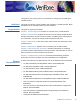
PREFACE This guide is your primary source of information for setting up and installing the VX 680 terminal. Audience Organization This guide is useful for anyone installing and configuring a VX 680 terminal. Basic descriptions of the terminal features are also provided. This guide is organized as follows: Chapter 1, Terminal Overview. Provides an overview of the VX 680 terminal. Chapter 2, Terminal Setup. Explains how to set up and install the VX 680 terminal.
P REFACE Conventions and Acronyms Conventions and Acronyms • Vx680 3G SW ERS 7-26, SPC268-025-01-A. • Vx680 3G PRD Rev A01, SPC268-028-01-A. • Vx680 3G EOS FRD REVB 02. This section describes the conventions and acronyms used in this guide. Document Various conventions are used to help you quickly identify special formatting. Table Conventions 1 describes these conventions and provides examples of their use.
P REFACE Conventions and Acronyms Acronym Definitions Various acronyms are used in place of the full definition. Table 2 presents acronyms and their definitions.
P REFACE Conventions and Acronyms 8 VX 680 INSTALLATION GUIDE
CHAPTER 1 Terminal Overview This chapter provides a brief description of the VX 680 terminal. This terminal features a large color and touchscreen display, fast processor, abundant memory, PCI 2.0, PCI 3.0, and PCI 3.1 security (VX 680 3G) as well as SIM support, and integrated contactless features. The VX 680 terminal is a portable, battery-powered device designed to fit comfortably during handheld consumer-facing applications. It features a vibrantly colored 3.
TERMINAL O VERVIEW Features and Benefits Features at a Glance The following are the features of VX 680: • 400 MHz ARM11 RISC processor delivers power and usability in a convenient “hand-over” design. • Multi-application operating environment. • Advanced memory architecture to meet tomorrow’s needs with support for 192 MB. • Backward compatibility with VeriFone solutions help reduces development costs. • Drop-resistant design minimizes breakage. • 32-bit processing and multi-tasking capabilities.
TERMINAL O VERVIEW Features and Benefits Performance and • Durability • Fast transactions due to powerful 400 MHz ARM11 processor. High-capacity 7.2 V 1800 mA Li-ion battery. • Standard base for drop-and-go charging or optional full-featured base with. spare battery charging. • USB ports for connection to supported USB peripherals. • Rounded corners and drop resistant to 3 feet on concrete floor to minimize breakage. • 192 MB of memory with optional removable SD flash memory.
TERMINAL O VERVIEW Features and Benefits 12 VX 680 INSTALLATION GUIDE
CHAPTER 2 Terminal Setup This chapter describes the terminal setup procedures. You will learn about: • Selecting Terminal Location. • Unpacking the Shipping Carton. • Examining Terminal Features. • Examining Connection Ports. • Establishing Telephone Line Connections. • VX 680 Bluetooth Support. • VX 680 3G and GPS Support • Installing the Paper Roll. • Installing and Replacing MSAM Cards. • Installing the SIM or R-UIM Card (GPRS, CDMA, and 3G Models).
TERMINAL S ETUP Selecting Terminal Location Selecting Terminal Location Use the following guidelines when selecting a location for your VX 680 terminal. Environmental • Factors The VX 680 unit is a portable terminal. Select a flat support surface, such as a countertop or table, to keep the terminal safe in between uses. • Do not use the terminal where there is high heat, dust, humidity, moisture, or caustic chemicals or oils.
TERMINAL S ETUP Unpacking the Shipping Carton Unpacking the Shipping Carton Open the shipping carton and carefully inspect its contents for possible tampering or shipping damage. The VX 680 device is a secure product and any tampering may cause the terminal to cease to function properly.
TERMINAL S ETUP Examining Terminal Features Examining Terminal Features Before you continue the installation process, notice the features of the VX 680 terminal (see illustration below).
TERMINAL S ETUP Examining Connection Ports • NOTE Examining Connection Ports A SAM (security access module) compartment, built into the bottom of the terminal inside the printer compartment. The VX 680 terminal contains an MSAM cardholder to support stored-value card programs or other merchant card requirements. VeriFone ships variants of the VX 680 terminal for different markets. Your terminal may have a different configuration.
TERMINAL S ETUP Examining Connection Ports VX 680 3G External VX 680 3G has a dedicated power barrel input for battery charging. This is located Power Port on the side of the device. Figure 5 Power Port Connection on a VX 680 3G Terminal USB Host Cable The VX 680 terminal also provides a 2 wire USB host port (VPN CBL268-003-01A) for supporting external peripherals. A connector adaptor provides for standard USB host connection for the Modem Dongle or the RS-232 UART dongle.
TERMINAL S ETUP Examining Connection Ports Multi-port Adapter An optional multi-port adapter (VPN 08643-01-R) provides connectivity for power, USB host, USB device, and COM1 (RS-232 UART). This cable is used only for deployment or development purposes. +12 VDC MIN I US BA COM 1 Figure 7 NOTE Multiport Adapter Connection to a VX 680 Terminal Other cables are available for different purposes. Check with your local VeriFone representative for further information.
TERMINAL S ETUP Examining Connection Ports USB Serial Dongle The USB Serial Dongle (VPN 24122-04-R) is designed to accomodate the RJ45 (RS-232 UART) connector and it may be purchased with the VX 680 terminal. The USB Serial Dongle can also be connected to the full-featured Base Station (see Attaching the USB Dongles to the Base Station). A Base Station may be purchased with the VX 680 terminal or purchased as a separate option.
TERMINAL S ETUP Establishing Telephone Line Connections Establishing Telephone Line Connections The VX 680 supports telephone line connections through a USB Modem Dongle connected to the phone cable. To connect a telephone line 1 Connect one end of the telephone cable to the USB Modem Dongle. 2 Connect the USB Modem Dongle to the terminal using the mini-HDMI Connector (VPN CBL268-003-01-A). 3 Route the other end of the telephone cable directly to a telephone wall jack.
TERMINAL S ETUP Installing the Paper Roll Installing the Paper Roll A fast, quiet thermal printer is built into the VX 680 terminal. Before you can process transactions that require a receipt or record, you must install a roll of thermal-sensitive paper in the printer. The ITP uses a roll of single-ply, thermal-sensitive paper 57 millimeters (2.24 inches) wide and 38 millimeters in diameter.
TERMINAL S ETUP Installing and Replacing MSAM Cards 6 Drop the paper roll into the printer tray. Figure 10 Loading Paper Roll 7 Pull paper up past the glue residue on the paper roll. 8 Close the paper roll cover by gently pressing directly on the cover until it clicks shut, allowing a small amount of paper past the glue residue to extend outside the printer door. CAUTION To prevent damaging the print roller, always gently press down on the paper roll cover to close it.
TERMINAL S ETUP Installing and Replacing MSAM Cards To Install and Replace 1 MSAM Power off the terminal. 2 Place the terminal upside down on a soft, clean surface to protect the display from scratches. 3 Unlock the printer cover. Figure 12 Unlocking the Printer Cover 4 Unscrew the latch to expose the MSAM compartment (see illustration below). Figure 13 Exposing the MSAM Compartment 5 Remove any previously installed MSAM card by pushing the snap that keeps the SAM in place.
TERMINAL S ETUP Installing and Replacing MSAM Cards SAM Figure 14 Installing MSAM Card 7 Screw the MSAM compartment latch. Figure 15 Closing the Printer Cover 8 Close the printer cover.
TERMINAL S ETUP Installing the SIM or R-UIM Card (GPRS, CDMA, and 3G Models) Installing the SIM or R-UIM Card (GPRS, CDMA, and 3G Models) The VX 680 terminal for GPRS modems supports the installation of a GSM SIM (Subscriber Identity Module), the VX 680 terminal for CDMA modems supports the installation of a R-UIM (Removable User Identity Module). Use the following procedure to install a SIM or R-UIM card. To install or replace 1 the card Turn off the terminal.
TERMINAL S ETUP Installing and Replacing SD Card 6,0 Figure 18 6,0 Inserting the SIM or R-UIM Card The VX 680 3G terminal has dual SIM support; both SIM slots are required to have SIM cards (from different networks), the dual SIM support allows the terminal to switch SIMs when it detects poor or no network state. 6,0 Figure 19 Inserting the SIM on VX 680 3G 6 Install the battery (see Figure 27).
TERMINAL S ETUP Installing and Replacing SD Card 5 Insert the SD Card into the cardholder. There is only one SIM/R-UIM slot and one SD slot (VX 680 3G has dual SIM support, see Figure 21). Make sure you insert the SD card into the SD slot, as shown in Figure 20. NOTE 6' Figure 20 Installing SD Card The same procedures apply when installing SD card on VX 680 3G (see Figure 21). 6' Figure 21 Installing SD Card on VX 680 3G 6 Install the battery (see Figure 27).
TERMINAL S ETUP VX 680 Bluetooth Support VX 680 Bluetooth Support The Bluetooth variant of the VX 680 terminal uses the Bluetooth Access Point (AP) Charging Base Station (VeriFone part numbers include XPBS019 for Silicon Labs dial modem; see your VeriFone representative for other available bases) to go online for authorization. Although up to eight VX 680 terminals can be registered with the same communications device, only one transaction may be undertaken at a time.
TERMINAL S ETUP VX 680 Bluetooth Support Modem Socket The Bluetooth AP Charging Base Station has a built-in modem for connecting to the standard telephone network. The Amber LED is only lit while the Bluetooth AP Charging Base Station is online. Modem Bluetooth RJ45 Power Figure 22 Connection Ports on Bluetooth AP Charging Base Station (Bottom View) Mounting the The illustation below describes the procedure for mounting the Bluetooth AP Bluetooth AP Charging Base Station to a vertical surface.
TERMINAL S ETUP VX 680 Bluetooth Support To Connect the Power 1 Pack Insert the round barrel connector into the power port on the Bluetooth AP Charging Base Station, as shown in the following illustration. Figure 24 Power Connection to the Bluetooth AP Charging Base Station 2 Insert the AC power cord into the power pack. 3 Plug the AC power cord into a wall outlet or powered surge protector. 4 Confirm that the Base Station is powered up as indicated by the solid green LED.
TERMINAL S ETUP VX 680 Bluetooth Support 2 Plug the modem cable directly to a telephone wall jack or use a ‘T’ connector if sharing the telephone line with other equipment. ETH Figure 25 NOTE 32 VX 680 INSTALLATION GUIDE Telephone Line Connection to the Bluetooth AP Charging Base Station The Bluetooth AP Charging Base Station MUST be connected to the telephone line at ALL times for all of the terminal’s facilities to function properly.
TERMINAL S ETUP VX 680 3G and GPS Support Connecting a LAN The VX 680 supports LAN connections through a Ethernet port connected to the cable to the LAN cable. Bluetooth AP Charging Base Station To connect a LAN Connect the LAN cable to the Ethernet port on the Bluetooth AP Charging Base cable to the Bluetooth Station, as shown in the figure below.
TERMINAL S ETUP Using the Smart Battery • NOTE 34 VX 680 INSTALLATION GUIDE • monitors state of charge (voltage and percentage of capacity) • communicates with the terminal (charge parameters and status), • determines full charge capacity (on charge cycle and uninterrupted discharge cycle) • automatically shuts down when cell voltage is extremely low A safety circuit that: • prevents cell damage from overcharge, over-discharge, or overheating • activates when the battery is left in an unuse
TERMINAL S ETUP Battery Behavior (No Power Cable) Battery Behavior (No Power Cable) The terminal shifts to cabled power mode and starts up automatically when the VX 680 is connected to a non-battery power source, regardless of the battery charge state. Manual Startup Hold the green key down for about 4 seconds until the terminal displays the startup screen. NOTE The 4-second power-up delay prevents terminal startup if the green key is accidentally held down.
TERMINAL S ETUP Installing the Smart Battery Installing the Smart Battery The VX 680 smart battery fits in a slot on the back of the VX 680 terminal, as shown in the following illustration. The locking tab clicks when the battery is in place. The slot is keyed, so that there is only one way to insert the battery. Figure 27 Removing the Smart Battery To remove the VX 680 smart battery, press the locking tab and pull the smart battery from its slot.
TERMINAL S ETUP Connecting the Terminal Power Pack Connecting the Terminal Power Pack After installing the smart battery, connect the VX 680 terminal to the provided power source for initial charging. CAUTION Using an incorrectly rated power supply may damage the terminal or cause it not to work as specified. Before troubleshooting, ensure that the power supply being used to power the terminal matches the requirements specified on the bottom of the terminal.
TERMINAL S ETUP Charging the Smart Battery Charging the Smart Battery After unpacking your VX 680 terminal, install the battery and connect the power pack to the unit for 6 hours or until fully charged. NOTE The terminal charges the VX 680 smart battery when the terminal is in the Base Station. For more information, see Mounting the Terminal Onto the Base Station. The smart battery has a safety circuit to protect the Li-ion cells from overcharging and over-discharging.
TERMINAL S ETUP Using the Base Station Using the Base Station The primary purpose of the Base Station is to charge the terminal battery and provide a docking station for the terminal after being used in pay-at-table environments. The Base Station can be positioned on a countertop or mounted to the wall. There are three types of Base Stations: the standard model, the full-featured model and the Bluetooth Access Point Charging Base. Standard Base The standard Base Station can charge the VX 680 terminal.
TERMINAL S ETUP Using the Base Station Bluetooth Access The Bluetooth Access Point Charging Base allows the VX 680 WiFi and Point Charging Base Bluetooth-enabled terminal to connect wirelessly to the network. It has three LED ( indicators: power indicator, Bluetooth traffic and modem traffic.
TERMINAL S ETUP Using the Base Station The base station’s status is shown on its different LED indicators: • The green LED indicates that the Bluetooth AP Charging Base Station is powered ON and capable of communication with other terminals. • The blue LED is lit when radio connection is made and a paired terminal is communicating with the Bluetooth AP Charging Base Station. • The amber LED is lit when the Bluetooth AP Charging Base Station is online and transmitting data using its internal modem.
TERMINAL S ETUP Powering Up the Base Station Powering Up the Base Station Use the procedure in this section to connect the VX 680 Base Stations to a power source. To power up the base 1 station Insert the round barrel connector of the power pack into the power port at the back of the Base Station. Figure 34 Connecting the Base Station to a Power Source 2 Insert the AC power cable into the power pack. 3 Plug the AC power cable into a wall outlet or power surge protector.
TERMINAL S ETUP Mounting the Terminal Onto the Base Station Mounting the Terminal Onto the Base Station The VX 680 terminal can be placed on the Base Station when not in use for continuous charging of its battery. External peripherals can also be attached to the terminal via USB dongles while it is on the Base Station (see Attaching the USB Dongles to the Base Station).
TERMINAL S ETUP Attaching the USB Dongles to the Base Station Attaching the USB Dongles to the Base Station With the VX 680 mounted on the Base Station, use the USB dongles to connect to external peripherals. Only one Modem Dongle and one Serial Dongle can be connected to the Base Station. A second Modem Dongle or a second Serial Dongle will be ignored by the terminal. NOTE The full-featured Base Station has USB ports for two external dongles. The standard Base Station does not have USB ports.
TERMINAL S ETUP Charging the Spare Battery on the Base Station 2 Place the spare battery pack onto the Base Station. Figure 37 Charging a Spare Battery Pack Using the Base Station 3 Place the VX 680 terminal onto the Base Station to charge both the spare and installed battery packs at the same time.
TERMINAL S ETUP Conducting Wireless Transactions Conducting To conduct a wireless transaction: Wireless • Ensure the terminal is in an optimal position for transmitting. Transactions • Conducting Smart Card Transactions Follow the on-screen instructions provided with your application. The smart card transaction procedure may vary from one application to another. Verify the procedure with your application provider before performing a smart card transaction.
TERMINAL S ETUP Using the Magnetic Card Reader Using the Magnetic Card Reader The VX 680 terminal supports credit/debit card transactions. To Conduct a Credit 1 or Debit Card Transaction Position a magnetic card with the stripe in the card reader and facing inward, toward the keypad. 2 To ensure a proper read of the magnetic swipe card, the user should insert the magnetic card from the top of the unit, as shown in the following illustration. 3 Swipe the card through the magnetic card reader.
TERMINAL S ETUP Using the Stylus 2 The stylus can be extended. Use this for touchscreen transactions as shown in the following illustration. Figure 42 Extending the Stylus 3 Loop a piece of cable or string (not supplied) through the stylus hole and the base of the printer cover to secure the stylus.
CHAPTER 3 Specifications This chapter discusses power requirements, dimensions, and other specifications of the VX 680 terminal. Power Rating DC Power Pack 12V DC 2.0 A UL, ITE listed, LPS power supply: a Input rated: 100-240V AC, 50/60 Hz b Output rated: 12V DC 2.
S PECIFICATIONS External Dimensions 50 VX 680 INSTALLATION GUIDE
CHAPTER 4 Maintenance The VX 680 terminal and Base Stations have no user-serviceable parts. Cleaning the Terminal To clean the terminal and Base Station, use a clean cloth slightly dampened with water and a drop or two of mild soap. For stubborn stains, use alcohol or an alcohol-based cleaner. CAUTION Never use thinner, trichloroethylene, or ketone-based solvents – they may cause deterioration of plastic or rubber parts.
M AINTENANCE Smart Card Reader 52 VX 680 INSTALLATION GUIDE
CHAPTER 5 VeriFone Service and Support For VX 680 terminal problems, contact your local VeriFone representative or service provider. For VX 680 product service and repair information: Returning a Terminal or Smart Battery for Service NOTE • USA – VeriFone Service and Support Group, 1-800-VeriFone (837-4366), Monday - Friday, 8 A.M. - 8 P.M.
VERI F ONE S ERVICE AND S UPPORT Returning a Terminal or Smart Battery for Service c Complete the Inquiry Contact Form at http://www.verifone.com/aboutus/ contact/contact_form.cfm. NOTE • Address the Subject box with to “VeriFone MRA Dept.” • Reference the model and part number in the Note box. One MRA number must be issued for each VX 680 terminal you return to VeriFone, even if you are returning several of the same model. 3 Describe the problem(s).
VERI F ONE S ERVICE AND S UPPORT Accessories and Documentation Accessories and Documentation Power Pack VeriFone produces the following accessories and documentation for the VX 680 terminal. When ordering, please refer to the part number in the left column. • VeriFone online store at www.store.verifone.com • USA – VeriFone Customer Development Center, 800-VeriFone (837-4366), Monday - Friday, 7 A.M. - 8 P.M.
VERI F ONE S ERVICE AND S UPPORT Accessories and Documentation Documentation 56 VX 680 INSTALLATION GUIDE VPN DOC268-001 VX 680 Certifications and Regulations Sheet VPN DOC268-002 VX 680 Quick Installation Guide VPN DOC268-004 VX 680 Reference Guide VPN DOC268-005 VX 680 Standard Base Quick Installation Guide VPN DOC268-006 VX 680 Full-Featured Base and Dongle Quick Installation Guide VPN DOC268-012 VX 680 CDMA Certifications and Regulations Sheet VPN DOC00301 Verix eVo Volume I: Operating
CHAPTER 6 Troubleshooting Guidelines The troubleshooting guidelines provided in the following section are included to help you install and configure your VX 680 terminal successfully. Typical examples of malfunction you may encounter while operating your VX 680 terminal and steps you can take to resolve them are listed in this chapter. If the problem persists even after performing the outlined guidelines or if the problem is not described below, contact your local VeriFone representative for assistance.
TROUBLESHOOTING G UIDELINES Smart Battery Does Not Charge Smart Battery Does Not Charge The VX 680 smart battery must initially receive a full charge to ensure proper operation. NOTE Spare Battery in Base Station Does Not Charge Blank Display 58 • Allow the VX 680 terminal to remain connected to the power pack for 6 hours to ensure the battery receives a full charge. • Li-ion batteries are not affected by shallow charging.
TROUBLESHOOTING G UIDELINES Terminal Does Not Dial Out Terminal Does If the terminal does not dial out: Not Dial Out • Check the telephone line connections. • Check that the telephone line is working by plugging it into a working telephone and listening for a dial tone. • Replace the telephone cable that connects the terminal with a cable you know is working correctly. • If the problem persists, contact your local VeriFone service provider.
TROUBLESHOOTING G UIDELINES Keypad Does Not Respond Keypad Does If the keypad does not respond properly: Not Respond • Check the terminal display. If it displays the wrong character or nothing at all when you press a key, follow the steps outlined in Transactions Fail to Process. Transactions Fail to Process • If pressing a function key does not perform the expected action, refer to the user documentation for that application to ensure you are entering data correctly.
TROUBLESHOOTING G UIDELINES Transactions Fail to Process Check the Telephone Line • Disconnect the telephone line from the VX 680 terminal and connect it to a working telephone to check for a dial tone. If there is no dial tone, replace the telephone cable. • If the problem appears to be with the telephone line, check with the party you are trying to call to see if their system is operational.
TROUBLESHOOTING G UIDELINES Transactions Fail to Process 62 VX 680 INSTALLATION GUIDE
INDEX A H accessories 55 documentation 56 ordering 55 power packs 55 telephone line cord 55 VeriFone cleaning kit 55 HDMI 7, 21 B Base Station 39 Bluetooth® Comm Base Station connector sockets 29 mounting the 30 power connection to the 31 requirements 14 telephone line connection to the 31 use of 20 C cleaning kit 55 connection ports 17 contact VeriFone 53 D dial out problems troubleshooting 59 displays troubleshooting 57, 58 documentation 55 acronym definitions 7 conventions 6 ordering 56 E electric
I NDEX R R RS232 UART 20 S service returning a battery for repair or replacement 53 returning a terminal for repair or replacement 53 SIM cards for GSM models 27 smart battery battery life 38 charging 38 conserving power 34 disposal 38 features 33 installation 36 recharging 38 troubleshooting 58 spare batteries charging on the Full-Featured Base Station 44 specifications DC power pack 49 power 49 temperature 49 standard Base Station 39 T technical support contacting VeriFone 53 returning a battery for re
I NDEX W VX 680 INSTALLATION GUIDE 65
VeriFone, Inc. 2099 Gateway Place, Suite 600 San Jose, CA, 95110 USA 1-800-VERIFONE www.verifone.com C E L N A I O T F N I E R D E I V NF O R VX 680 Installation Guide VeriFone Part Number DOC268-003-EN-E, Revision E.1 I V E S N O I 1 .