
User's Manual
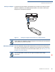
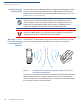
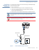
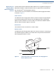
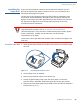
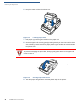
Table Of Contents
- VX 680
- Contents
- Preface
- Terminal Overview
- Terminal Setup
- Selecting Terminal Location
- Unpacking the Shipping Carton
- Examining Terminal Features
- Examining Connection Ports
- Establishing Telephone Line Connections
- VX 680 Bluetooth® Support
- Installing the Paper Roll
- Installing and Replacing MSAM Cards
- Installing the SIM or R-UIM Card (GPRS and CDMA Models)
- Installing and Replacing SD Card
- Using the Smart Battery
- Battery Behavior (No Power Cable)
- Installing the Smart Battery
- Removing the Smart Battery
- Connecting the Terminal Power Pack
- Charging the Smart Battery
- Using the Base Station
- Powering Up the Base Station
- Mounting the Terminal Onto the Base Station
- Attaching the USB Dongles to the Base Station
- Charging the Spare Battery on the Base Station
- Conducting Wireless Transactions
- Conducting Smart Card Transactions
- Conducting Bluetooth® Transactions
- Using the Magnetic Card Reader
- Using the Stylus
- Specifications
- Maintenance
- VeriFone Service and Support
- Troubleshooting Guidelines
- Index
- Contact VeriFone

TERMINAL SETUP
Establishing Telephone Line Connections
VX 680 I
NSTALLATION GUIDE 23
Establishing
Telephone Line
Connections
The VX 680 supports telephone line connections through a USB Modem Dongle
connected to the phone cable.
To connect a telephone line
1 Connect one end of the telephone cable to the USB Modem Dongle.
2 Connect the USB Modem Dongle to the terminal using the mini-HDMI
Connector (VPN CBL268-003-01-A).
3 Route the other end of the telephone cable directly to a telephone wall jack.
Figure 8 VX 680 USB Modem Dongle Connection
NOTE
The VX 680 WiFi/BT variant does not support the USB modem dongle
connection.
WARNING
To reduce the risk of fire, use only No. 26 AWG or larger UL Listed or CSA
Certified Telecommunication Line Cable.
USB HOST CABLE
USB MODEM DONGLE