
User's Manual
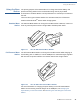
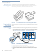

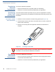
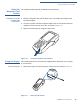

Table Of Contents
- VX 680
- Contents
- Preface
- Terminal Overview
- Terminal Setup
- Selecting Terminal Location
- Unpacking the Shipping Carton
- Examining Terminal Features
- Examining Connection Ports
- Establishing Telephone Line Connections
- VX 680 Bluetooth® Support
- Installing the Paper Roll
- Installing and Replacing MSAM Cards
- Installing the SIM or R-UIM Card (GPRS and CDMA Models)
- Installing and Replacing SD Card
- Using the Smart Battery
- Battery Behavior (No Power Cable)
- Installing the Smart Battery
- Removing the Smart Battery
- Connecting the Terminal Power Pack
- Charging the Smart Battery
- Using the Base Station
- Powering Up the Base Station
- Mounting the Terminal Onto the Base Station
- Attaching the USB Dongles to the Base Station
- Charging the Spare Battery on the Base Station
- Conducting Wireless Transactions
- Conducting Smart Card Transactions
- Conducting Bluetooth® Transactions
- Using the Magnetic Card Reader
- Using the Stylus
- Specifications
- Maintenance
- VeriFone Service and Support
- Troubleshooting Guidelines
- Index
- Contact VeriFone

TERMINAL SETUP
Powering Up the Base Station
42 VX 680 INSTALLATION GUIDE
Bluetooth
®
Access
Point Charging Base
The Bluetooth
®
Access Point Charging Base allows the VX 680 WiFi and
Bluetooth
®
-enabled terminal to connect wirelessly to the network. It has three
LED indicators: power indicator, bluetooth traffic and modem traffic.
Figure 29 The VX 680 Bluetooth Access Point Charging Base Station
Powering Up the
Base Station
Use the procedure in this section to connect the VX 680 Base Stations to a power
source.
To power up the base
station
1 Insert the round barrel connector of the power pack into the power port at the
back of the Base Station. For Bluetooth
®
Access Point Charging Base Station,
see Power Connection to the Bluetooth
®
AP Charging Base Station.
Figure 30 Connecting the Base Station to a Power Source
2 Insert the AC power cable into the power pack.
3 Plug the AC power cable into a wall outlet or power surge protector.
4 Confirm that the Base Station is powered up as indicated by the solid green
LED.
(