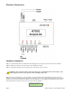
AcquiLite EMB – Data Acquisition Server Obvius, LLC Installation and Operation Manual Model A7810 Date Aug 10, 2011 Page 1 A7810 AcquiLite – Data Acquisition Server
Copyright Information Copyright © 2001 - 2011 by Obvius Obvius and AcquiLite are trademarks of Obvius Holdings LLc Other brand and product names are trademarks or registered trademarks of their respective holders. U.S. Government Restricted Rights: Use, duplication or disclosure by the Government is subject to restrictions set forth in subparagraph (a) through (d) of the Commercial Computer Restricted Rights clause at FAR 52.
Table of Contents Overview....................................................................................................................................................................................................... 4 Installation Checklist..................................................................................................................................................................................... 4 Markings and Symbols:.........................................................
Overview The AcquiLite™ data acquisition system is designed to allow owners and managers of commercial and industrial facilities with a cost-effective means of gathering crucial information in a timely manner. To meet these requirements, the AcquiLite™ system provides the installer with all the tools necessary to install and configure the hardware and software with a minimum of time and investment.
Hardware Overview A7810 Features and Specifications Processor Arm9 embedded CPU Operating System Linux 2.
Electrical Connections Hardware Installation Step 1 - Unpack materials: Remove all materials from shipping box and verify all required components are available Step 2 - Mount the AcquiLite on the wall, panel or other appropriate location. Step 3 – Attach pulse output devices to the pulse inputs on the A7810. For dry-contact WARNING: After wiring the A7810, remove all scraps of wire or foil shield from the electrical panel. This could be dangerous if wire scraps come into contact with high voltage wires.
This indicates that the AcquiLite has loaded properly and is ready for configuration and connection to the network and sensors. If the “Alive” light does not come on or the LCD display does not cycle to the above screen, verify that the power wires and connector are secure, and are providing required power as specified. If after cycling the power, the unit still does not power up (or if an error message appears in the LCD display) contact technical support.
B. Press the Select button once to select the TCP/IP Config menu options, first of which is DHCP: [TCP/IP Config] DHCP on/off C. Press the Menu button once to see the TCP/IP IP Address menu: [TCP/IP Config] IP Address D. Press the Select button again to select the IP Address menu: [IP Address] 192.168.40.50 E. At this point, the cursor on the display will be blinking on the first number in the IP address on the second line. F.
building LAN, or directly to the AcquiLite. Attach the laptop to the AcquiLite or LAN as shown in figure 6, Ethernet hookup. Step 2 - Attach the Laptop to the AcquiLite or to the LAN. The A7810 will automatically detect whether a direct or crossover cable is required, and will reverse polarity accordingly. This feature will allow you to use either a straight Ethernet cable or a crossover Ethernet cable interchangeably.
AcquiLite Administration Overview The AcquiLite should now be available on the local area network for you to access using a web browser such as Internet Explorer or Netscape. Step 1 - Use your web browser to connect to the AcquiLite by entering http://192.168.40.50/setup/ Where 192.168.40.50 is the IP address displayed on the on the AcquiLite LCD display.
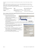
Security The AcquiLite has three levels of security. These are “operator”, “user” and “admin”. When using a browser to access the AcquiLite, basic http authentication is used to prompt your browser for a username and password. The admin account uses “admin” as the default password. To change the password, select the Accounts menu from the left side tree display. Next, select the account name. Click the “Change Password” button to set a new password for the selected account.
Note: not all Modbus devices have built in driver support in the AcquiLite. If a device appears in the list with “Unknown” in the status column, you may need to upgrade the firmware on the AcquiLite to access the device. At the bottom of the device list page under the Type column, a link is shown that will show all the Modbus devices with built in driver support provided in the firmware. Use the System/Firmware update page to check for newer versions of the firmware. The Obvius.
Device Details. The device detail page will show a list of all the pulse input data points, alarm settings and console options. The data point names for most devices are automatically entered. At the top of the page, the status of the device is shown. This usually reports “ok” however it can include error information if the device is not responding properly. A list of device errors is available in the log file details section of this manual. At the bottom of the page, several buttons are present.
Device Configuration When the “configure” button is clicked from the device details page, the screen will be refreshed, with the same information, however the device name, alarm settings and console checkbox will be available. Device Name: This field allows you to specify a name for the device such as “main building power” or other useful name to indicate the location or function of the device. A name must be assigned to a device before the AcquiLite will log data for it.
Manual Device Add Options Modbus devices may be added manually by clicking on the “add” link on the bottom of the Modbus device list page. This option is intended for use when adding devices to the configuration profile prior to installing the physical hardware, or configuring Modbus/TCP devices that will not automatically populate in the Modbus device list. The manual setup page has several options that must be configured before the AcquiLite will recognize the Modbus device.
Troubleshooting Pulse inputs If the device you have attached does not appear in the Modbus device list, check the following: ● Verify the pulse input connections are correct . ● Verify the status LED blinks for the specific pulse input in question. Try bridging the two terminals at the input of the AcquiLite to verify the input LED turns on. ● Bridge the terminals of the pulse output meter and verify the input LED turns on. This will verify the wiring to the meter is correct.
SMTP Mail Server Address: The IP address of the email server on the LAN that will process and forward the email message to the recipient. Sender Address: The address that will be used in the “From:” line of the email. This is helpful in identifying the source of the alarm email message. If your SMTP mail server has junk filtering, you may be required to use a sender address that matches a mailbox address on the SMTP mail server; check with your mail server administrator for specific details on this issue.
this field blank. ● DNS 1, DNS2: These are the primary and secondary DNS servers. If you are using a dialout connection, these must be set to the DNS server provided by your dialup ISP. If you only use the AcquiLite on a crossover cable and/or dialin mode, you should leave these blank. ● DHCP (enable/disable) If you LAN has a DHCP server, you may enable this option and remove the previous options for IP, netmask, gateway, and DNS. Check with your LAN administrator first. ● HTTP Proxy.
Time Server: Specify the DNS name or IP address of your time server. The default “time.obvius.com” can be used if the AcquiLite has a connection to the Internet. The AcquiLite will attempt to synchronize time with the time server every upload session. This will ensure that the clock is checked and adjusted at a minimum of once per day. Typically, the synchronization will align the clock to within +-1 second of the internet time source or atomic clock.
Last Data Upload log: This log file contains a report from the last data upload attempt to remote database/webservers such as BMO. This log will show if any log files are being rejected by the dabase/webserver, or if the network is not allowing a connection. Last Modem Connection log: This log file shows the details of the modem operation including modem connection quality parameters. This is updated ever time the modem makes a dialin or dialout connection.
Ethernet IP address [192.168.10.50], mask [255.255.255.0] Local subnet [192.168.10.0] to [192.168.10.255] Ping ethernet ip address [192.168.10.50]: Success Starting system debug logger Dialout not enabled, using ethernet LAN connection. Ping ethernet gateway [192.168.10.1]: Success Ping DNS #1 [192.168.10.1]: Success The DNS #2 server address is not configured. Resolving time server [time.obvius.com] to an IP address: Success. Got [70.99.203.62] Ping time server [time.obvius.
Modbus Status Data Upload Show Serial # Upload Data Now Modules Disable All (previous menu) Shutdown Reboot (previous menu) The TCP/IP sub menu will allow you to configure the Ethernet settings for the AcquiLite. To edit the IP settings, use the Menu button to change options, and press the Select button to edit the option. Once selected, you will see the current value displayed and a blinking square cursor on the first character. Press the Menu button to change the character or digit.
Erase log/config (previous menu) The Check Flash Disk option will force the AcquiLite to check the entire flash disk for file system integrity. This will require you to reboot the AcquiLite. The Enable Console feature will provide a shell prompt on the serial port for remote diagnostics. This is intended to be used by Obvius technical support only.
Date/Time: The date/time column reports the time at which data was logged from the Modbus device. Note: this is not necessarily the time at the start of the log cycle. Users with large number of devices may notice some of the Modbus devices at higher address numbers report 1 or 2 seconds after the first Modbus devices. This is because the 9600baud speed of the Modbus loop is not fast enough to log all Modbus devices in less than 1 second.
accept blank or NULL as a valid entry in a data table to represent invalid data. For data exported from the BMO website, the columns that are invalid (NULL) are reported as blank fields. This makes it easier to import into MS Excel as blank cells. With the current firmware, the AcquiLite will report blank fields rather than "NULL" to make direct import of data from the AcquiLite easier, as well as reduce the file size.
log file storage area is more than 75% full. ● Allow remote modbus device configuration: If enabled, users may remotely configure alarms and other modbus device features on the BMO website. When the AcquiLite uploads data to the BMO website, it will also download any new configuration information as needed. Note: if configuration changes are made to the AcquiLite, those changes will be uploaded to the BMO site.
Enertrax download direct from the AcquiLite Obvius provides a free tool called Enertrax DL that can automate the process of downloading log data from the AcquiLite to your Windows PC hard drive. Enertrax DL can merge new log data into existing log files on your computer as well as provide configuration information about the AcquiLite. Enertrax DL can also be configured to make LAN or Dialup calls to one or more AcquiLite or AcquiSuite data acquisition servers. Enertrax DL can be obtained from the obvius.
Linking to AcquiLite Device Status Pages It may be helpful to create a shortcut or a hyperlink on another web page that will direct the browser to bring up a specific device status page in your browser. To do this, right click on the page and select properties. The URL for the page will be shown on that dialog. Simply copy/paste this URK into your link. The AcquiLite can provide Modbus device data in XML format.
Mechanical Drawings The AcquiLite uses a plastic enclosure that is approximately 4” x 4.25” x 2” deep. The AcquiLite has 4 mounting holes for use with a #6 screw. The drawing above shows the relative position of the mounting holes.