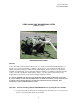
Veris Technologies Pub. #OM 1CM02-1 2000XA Soil EC Mapping System Operating Instructions Table of Contents P. 3-7 Installation and set-up P. 7-11 Maintenance and Lubrication P. 12-15 Field Operations P. 17-18 Troubleshooting P. 19-20 Updating Firmware P.
Veris Technologies Pub. #OM 1CM02-1 VERIS 2000XA SOIL EC MAPPING SYSTEM (software v.1.76e) ) OPERATING INSTRUCTIONS Warranty Veris Technologies warrants this product to be free of defects in materials and workmanship for a period of one (1) year from the date of delivery to the purchaser. Veris Technologies will repair or replace any product returned to Salina, Kansas, which appears upon inspection to be defective in materials or workmanship.
Veris Technologies Pub. #OM 1CM02-1 2) 3) 4) 5) Never allow anyone to ride on the implement during operation. Lift the implement only with the provided ratchet jack. Properly support the unit before performing any adjustment or maintenance. Due to its small size and narrow design, it is not intended for high-speed travel on public roads. If you choose to do so, contact your state Department of Transportation for safety markings and guidelines. Veris Technologies suggests trailer transport.
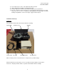
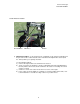
Veris Technologies Pub. #OM 1CM02-1 Below is a rear view of the instrument Serial Port for GPS Signal Serial Port for Listening Computer Power Power cable Switch Port Signal Port For signal cable or Test Load Connect GPS cable to GPS INPUT serial port on back of instrument. The Veris instrument is designed to accept GPS input in NMEA format via an RS232 connector. Note: GPS signals are frequently affected by electrical interference from magneto electrical systems.
Veris Technologies Pub. #OM 1CM02-1 5) If the readings vary greatly (more than one whole number) contact our service department. 6) Once the test is complete, remove the test load and reinstall the implement signal cable. Test Load Note: It is advisable to conduct this test as a routine check to ensure that you are obtaining reliable data. Note: This equipment has been tested and found to comply with the limits for a Class A digital device, pursuant to Part 15 of the FCC rules.
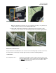
Veris Technologies Pub. #OM 1CM02-1 Coulter Electrode Isolation Grounded bolt Ohmmeter Coulter 3) Implement Test Box – To properly measure conductivity, good electrical continuity must be present from the coulter electrode to the instrument. The Implement Test Box (Part No. 15231) allows you to quickly check this. Use the following method: a) Connect the signal cable to the terminal on the test box.
Veris Technologies Pub. #OM 1CM02-1 Note: It is advisable to perform this test on a routine basis (weekly or every 20-25 hours of data collection) to ensure you are obtaining reliable data. 4) Hitch height—adjust hitch on implement so implement operates level when coulter electrodes are 1-2” in the soil. The hitch is designed with four possible height positions.
Veris Technologies Pub. #OM 1CM02-1 Pivot grease zerks Rachet jack -- 40 hour intervals Grease zerks Electrode coulters Pivot -- In all but the most extremely rocky conditions, the coulter electrodes should not flex in the field, thus minimal movement will be realized at the pivot. 80-hour intervals should be sufficient.
Veris Technologies Pub. #OM 1CM02-1 Grease zerk Hubs -- Use good quality wheel bearing or lithium grease for lubrication, but we suggest that you grease the hubs sparingly. Over-lubricating the hub will result in pre-mature seal failure, and an excessive amount of grease in the hub cap/commutator. On an interval of 150 hours, 1-2 strokes of grease should be sufficient.
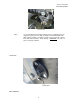
Veris Technologies Pub. #OM 1CM02-1 Commutators-- The spring-loaded commutators are located in the center of each coulter electrode hub cap. They are factory preset, and should not need routine adjustment. If a continuity test shows abnormally high resistance, the commutators should be checked. This may be performed in the following manner: 1) Remove the 3/8” allen head set screw. 2) Remove the commutator by turning counter-clockwise.
Veris Technologies Pub. #OM 1CM02-1 Cap Commutator Set screw Spindle Note: If you are still unable to obtain favorable resistance readings, check for excessive corrosion at the coulter blade mounting bolts, or the terminal located near the coulter pivot. ANNUAL MAINTENACE Wheel hubs -- Coulter electrode hubs -- On and annual basis, disassemble, clean, and properly repack the wheel hubs with suitable wheel bearing grease. It is advisable to replace the seals.
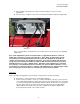
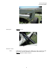
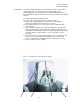
Veris Technologies Pub. #OM 1CM02-1 Swing arm Field Operations Soil Contact Begin field operation by lowering unit into soil. For good electrical conductivity, all coulter electrodes must be in direct contact with the soil, at all times and in every region of the field. A depth of 1-2” is recommended. To insure this depth is consistently achieved, 300-350 lbs. of additional weight are normally required. Veris offers optional weights and mounting hardware that can be installed on the 2000XA.
Veris Technologies Pub. #OM 1CM02-1 Field Condition Field should be in a uniform state. Mapping after intensive primary tillage is not recommended. The soil must have a minimum of 10% available water, and cannot be frozen. If rocky conditions exist, you may wish to consider the optional coulter rock guard kit , PN 15170.
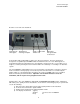
Veris Technologies Pub. #OM 1CM02-1 Wide Setting GPS Settings 1. Make sure that the GPS is plugged into the proper DB-9 input. Looking at the back of the instrument, the GPS should be plugged into the leftmost input port. A null modem adapter should not be used. 2. Make sure that the GPS has power and has been turned on long enough to start outputting data. Some units may require a couple minutes to start while others may require much longer. 3.
Veris Technologies Pub. #OM 1CM02-1 Signal Cable Attach the signal cable to the quick connect coupler at front of frame, and to Signal Port on back of instrument Instrument display readings Here are the display readings that you will see when operating the system, the meaning of each, and what choices you have at each step. Booting up… Meaning: The unit is ready to operate. The computer is informing you of how much of its internal memory is available.
Veris Technologies Pub. #OM 1CM02-1 no parity and 1 stop bit. A null modem adapter is required.) If you press 3, the system will tell you it’s ok to shut off power. Meaning: The unit is letting you know the name of the map file it is creating, in case you want to record it along with any other information about the field.
Veris Technologies Pub. #OM 1CM02-1 This is the File Management menu. Pressing 1 will copy all data files present on the Instrument to the removable CF card. Pressing 2 will bring up the following screen: Selecting 1 will delete ALL data files from the Instrument. Verify that all data files are backed up to a computer before proceeding. Pressing 3 in the File Management menu will bring up the following screen: Selecting 1 will delete ALL data files from the CF card.
Veris Technologies Pub. #OM 1CM02-1 TROUBLESHOOTING Map doesn’t match known or expected soil types -1. 2. 3. 4. Check electrical continuity using Implement Test Box as discussed on Page 6. Check isolation of coulter electrodes (pg. 5) Map additional fields to see if similar condition results Contact Veris Service Department No conductivity readings on instrument display-1. 2. 3. Check for excessive corrosion on coulter terminasl.
Veris Technologies Pub. #OM 1CM02-1 longitude should appear on the instrument display and the instrument should not beep when the vehicle is in motion (provided the conductivity readings are positive). Troubleshooting steps 6. Make sure that the GPS is plugged into the proper DB-9 input. Looking at the back of the instrument, the GPS should be plugged into the leftmost input. A null modem adapter should not be used. 7.
Veris Technologies Pub. #OM 1CM02-1 CF card Troubleshooting: Using off-the-shelf CF cards rather than the ones supplied by Veris Technologies, may cause any of the following problems: -instrument won’t boot up -instrument won’t log any data -GPS signal not recognized Veris CF cards contain an ATA front end--circuitry that makes the CF card look like a hard drive to the instrument. Most CF cards don't have this.
Veris Technologies Pub. #OM 1CM02-1 5. Left mouse click on the green arrow in your computer’s system tray and again on the button “Stop USB Mass Storage Device”. 6. Click “OK” on the window that appears. It is now safe to remove the card reader from your computer. 7. Insert CompactFlash card into the Instrument and restart the Instrument. During bootup, the following screen will appear: **NOTE: The instrument WILL NOT function without the CF card inserted.
Veris Technologies Pub. #OM 1CM02-1 Compact Flash card formatting Insert a Compact Flash card into a CF card reader which connected to your computer. Open “My Computer” folder. Right click on the CF card icon, and select the “Format”. In the format window, click on the file system tab and select “FAT” not “FAT32”. Then press “Start”. When complete, remove the card.