Veris Technologies Pub. #OM 1CM02-1 3100 Soil EC Mapping System Operating Instructions Table of Contents P. 3-7 Installation and set-up P. 8-12 Maintenance and Lubrication P. 13-16 Field Operations P. 17-18 Troubleshooting P. 19-20 Updating Firmware P.
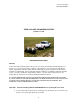
Veris Technologies Pub. #OM 1CM02-1 VERIS 3100 SOIL EC MAPPING SYSTEM (software v.1.77d) OPERATING INSTRUCTIONS Warranty Veris Technologies warrants this product to be free of defects in materials and workmanship for a period of one (1) year from the date of delivery to the purchaser. Veris Technologies will repair or replace any product returned to Salina, Kansas, which appears upon inspection to be defective in materials or workmanship.
Veris Technologies Pub. #OM 1CM02-1 2) 3) 4) 5) Never allow anyone to ride on the implement during operation. Lift the implement only with the provided ratchet jack or optional hydraulic cylinder. Properly support the unit before performing any adjustment or maintenance. Do not tow the implement on public roads without the optional light package, or without the proper safety equipment and licensing as required by your State Department of Transportation.
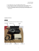
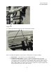
Veris Technologies Pub. #OM 1CM02-1 Make sure that you have received all of these components in your EC Package. Mount instrument in a location that is as free as possible from dust, vibration, and electrical interference. Display should be visible to operator and shielded from direct sunlight.
Veris Technologies Pub. #OM 1CM02-1 5) If the readings vary greatly (more than one whole number) contact our service department. 6) Once the test is complete, remove the test load and reinstall the implement signal cable. Test Load Note: It is advisable to conduct this test as a routine check to ensure that you are obtaining reliable data. Note: This equipment has been tested and found to comply with the limits for a Class A digital device, pursuant to Part 15 of the FCC rules.
Veris Technologies Pub. #OM 1CM02-1 Support here 3) Install tongue with two 5/8’ X 41/2” bolts and torque to 170 ft lbs Prior to operating the implement for the first time, it is important to check the following: 1) All fasteners – some may have loosened during shipment. 2) Coulter electrode isolation – check so see that no metal part of the any coulter electrode is in contact with the implement frame.
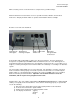
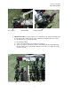
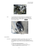
Veris Technologies Pub. #OM 1CM02-1 No continuity Grounded Bolt Coulter terminal 3) Implement Test Box – To properly measure conductivity, good electrical continuity must be present from the coulter electrode to the instrument. The Implement Test Box (Part No. 10759) allows you to quickly check this. Use the following method: a) Connect the signal cable to the terminal on the test box.
Veris Technologies Pub. #OM 1CM02-1 c) Continue to check each coulter electrode in succession, left to right. d) If any coulter electrode exhibits no continuity or resistance higher than 2 ohms, refer to the maintenance or trouble shooting sections for possible causes. Note: It is advisable to perform this test on a routine basis (weekly or every 20-25 hours of data collection) to ensure you are obtaining reliable data.
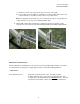
Veris Technologies Pub. #OM 1CM02-1 Pivot grease zerks Rachet jack -- 40 hour intervals grease zerks Electrode coulters Pivot -- In all but the most extremely rocky conditions, the coulter electrodes should not flex in the field, thus minimal movement will be realized at the pivot. 80-hour intervals should be sufficient.
Veris Technologies Pub. #OM 1CM02-1 grease zerk Hubs -- Use good quality wheel bearing or lithium grease for lubrication, but we suggest that you grease the hubs sparingly. Over-lubricating the hub will result in pre-mature seal failure, and an excessive amount of grease in the hub cap/commutator. On an interval of 150 hours, 1-2 strokes of grease should be sufficient. Grease zerk ADJUSTMENTS Commutators-- The spring-loaded commutators are located in the center of each coulter electrode hub cap.
Veris Technologies Pub. #OM 1CM02-1 4) If the plunger will not move freely, replace, and coat with di-electric silicone grease. 5) If the commutator appears to be in good working order, reinstall in the hub, and adjust until it bottoms against the spindle end. Rotate 1/2 turn backward to allow adequate clearance. Improper adjustment will result in premature failure (too little tolerance) or poor continuity (too much tolerance). 6) Reinstall locking set screw and tighten firmly on top of commutator.
Veris Technologies Pub. #OM 1CM02-1 Coulter electrode hubs -- The coulter electrode hubs operate in a significantly harsh environment, and annual inspection is of utmost importance. The double-lip seals are designed to keep grease in, and contaminates out, but they are the cause of practically all hub failures. It is advisable to disassemble, clean, repack, and re-install annually.
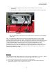
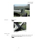
Veris Technologies Pub. #OM 1CM02-1 Field Operations Soil Contact Begin field operation by lowering unit into soil. For good electrical conductivity, all coulter electrodes must be in direct contact with the soil, at all times and in every region of the field. A depth of 1-2” is recommended. To insure this depth is consistently achieved, 400-600 lbs. of additional weight are normally required. Veris offers optional weights, or they can be supplied by the customer.
Veris Technologies Pub. #OM 1CM02-1 Signal Cable Attach the signal cable to the quick connect coupler at front of frame, and to Signal Port on back of instrument Instrument display readings Here are the display readings that you will see when operating the system, the meaning of each, and what choices you have at each step. Booting up… Meaning: The unit is ready to operate. The computer is informing you of how much of its internal memory is available.
Veris Technologies Pub. #OM 1CM02-1 Creating a new map file… Meaning: The unit is asking whether you’re ready to start mapping. Choices: If you press 1, you’ve initiated the beginning of a map file. Command #2 is for sending a data string to a second data-logging device. (The conductivity output format is 9600 baud, 8 data bits, no parity and 1 stop bit. A null modem adapter is required.) If you press 3, the system will tell you it’s ok to shut off power.
Veris Technologies Pub. #OM 1CM02-1 If any old data files are present on the Instrument, pressing any key at the main title screen will bring up the following screen: Pressing 1 will proceed into managing the files on the Instrument and CF card. Pressing 2 will continue to the main menu. This is the File Management menu. Pressing 1 will copy all data files present on the Instrument to the removable CF card.
Veris Technologies Pub. #OM 1CM02-1 TROUBLESHOOTING Map doesn’t match known or expected soil types -1. 2. 3. 4. Check electrical continuity using Implement Test Box as discussed on Page 6. Check isolation of coulter electrodes (pg. 5) Map additional fields to see if similar condition results Contact Veris Service Department No conductivity readings on instrument display-1. 2. 3. 4. No continuity on coulter electrode # 2 or # 5. Check for excessive corrosion on coulter terminal.
Veris Technologies Pub. #OM 1CM02-1 Troubleshooting GPS Problems-This is a problem-solving guide for the user who is not able to obtain a position from the GPS when it is connected to the Veris 3100 instrument. Note that when the system is working properly, the latitude and longitude should appear on the instrument display and the instrument should not beep when the vehicle is in motion (provided the conductivity readings are positive). Troubleshooting steps 6.
Veris Technologies Pub. #OM 1CM02-1 CF card Troubleshooting: Using off-the-shelf CF cards rather than the ones supplied by Veris Technologies, may cause any of the following problems: -instrument won’t boot up -instrument won’t log any data -GPS signal not recognized Veris CF cards contain an ATA front end--circuitry that makes the CF card look like a hard drive to the instrument. Most CF cards don't have this.
Veris Technologies Pub. #OM 1CM02-1 1. 2. 3. 4. 5. Shut Instrument off and remove CompactFlash card. Always turn the instrument off before removing the CF card. Insert CompactFlash card into CompactFlash card USB reader. Plug USB reader into computer. Copy the file VERIS.BAT from your computer to the CompactFlash card. Left mouse click on the green arrow in your computer’s system tray and again on the button “Stop USB Mass Storage Device”. Click “OK” on the window that appears.
Veris Technologies Pub. #OM 1CM02-1 Compact Flash card formatting Insert a Compact Flash card into a CF card reader which connected to your computer. Open “My Computer” folder. Right click on the CF card icon, and select the “Format”. In the format window, click on the file system tab and select “FAT” not “FAT32”. Then press “Start”. When complete, remove the card.