Trouble-shooting 2000 XA, 3100, 3150 Soil EC Mapping System (Refer to Operations Manual for complete instructions, including software installation, safety, maintenance, and troubleshooting.) Table of Contents Procedure #1: EC Surveyor Instrument Signal Testing Procedure #2: Testing Electrical Continuity Procedure #3: Diagnosing and Correcting EC Signal Problems.
Procedure #1: EC Surveyor Instrument Signal Testing Perform this test daily or every 10 hours of data collection to ensure you are obtaining reliable data, and whenever EC data is questionable. The purpose of this test is to insure that the instrument is performing properly. The EC Surveyor is shipped with an Instrument Test Load (Part No. 10447) that will enable you to quickly check the instrument to ensure that it is functioning properly.
Procedure #2: Testing Electrical Continuity Perform this test daily or every 10 hours of data collection to ensure you are obtaining reliable data, and whenever EC data is questionable. The purpose of this test is to insure that each coulter-electrode has an uninterrupted signal path from the EC Surveyor to the disk blade. Think of each coulter-electrode and its wire path as a ‗channel‘. On a 3100 and 3150, there are 6 signal channels that must be clear and isolated from each other (4 on a 2000XA).
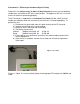
Remove the signal cable from the EC Surveyor and connect it to the terminal on the test box. If you have hard-wired the signal cable extension into the cab, making it difficult to reach the implement with the cable end, you may want to purchase an extension cable from Veris (part #12269). This cable attaches to the signal cable end and allows you to position the Signal Test Box in close proximity to the coulter-electrodes. Signal extension cable (from implement) Figure 2.
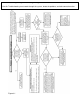
Procedure #3: Diagnosing and Correcting EC Signal Problems. Use this Troubleshooting tree to work through the system, locate the problem, and take corrective action. Figure 3.
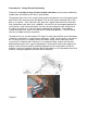
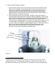
Coulter Electrode FunctionsEach coulter electrode on the implement is part of a pair, and each pair has a distinct function. a) Coulters 1 & 6 are the Deep EC receptors. If you are seeing problems only with the ―Deep‖ readings, focus on testing continuity on these two coulter-electrodes. b) Coulters 2 & 5 are the ―charged‖ coulters that inject the voltage into the soil.
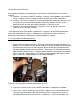
problem is not with the wiring harness or signal cable extension. It is most likely in the terminal connector wire. Check resistance in it by placing one ohmmeter lead on the coulter wire terminal bolt and the other lead in the end of the terminal wire socket. Replace connector wire (PN 14226) as necessary. Figure 3.3 Testing cable at end of signal cable wiring harness Figures 3.4 ab. a. Separating sure-seal connector b. Testing terminal connector wire 4.
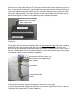
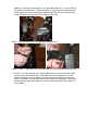
4 3 2 5 6 1 Figures 3.5 a and b. Checking continuity of signal extension cable with one ohmmeter lead contacting pins in extension cable end, and other lead contacting corresponding test box terminal. 5. To ohm out the wiring harness, disconnect the serial cable extension from the implement and check continuity through the harness as shown in Figures 10a and 10b. While doing so, check the pins and the sockets of the 6-pin connector for corrosion and fit.
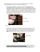
B. Testing Coulter-Electrode continuity 1. Place ohmmeter lead on terminal wire bolt and other lead on disk blade. Rotate blade ¼ turn. If readings are consistently above 2 ohms, check for excessive corrosion at the coulter blade mounting bolts, or the terminal located near the coulter pivot. Make sure that high ohm readings are not due to poor contact between blade and ohmmeter lead. Re-test holding lead firmly against edge of blade, removing rust or paint if necessary. 2.
cable, causing channels to short out. Or, one of the coulter-electrodes is no longer insulated properly from the frame or adjacent coulter-electrodes. 1. If EC readings do not drop to –1 when unit is raised, disconnect signal cable extension from implement. If readings don‘t drop to –1, the problem is with the signal cable extension. If readings show -1, re-insert the signal cable extension into the implement. Disconnect the sure-seal terminal connector wire from each coulter electrode.
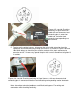
individual coulter electrode, and the other to a grounded fastener on the frame. If the coulter electrode is properly isolated, no reading will be obtained. Make sure that all electrode coulter clamp bolts are properly tightened to prevent lateral movement of the coulter electrode. no continuity grounded bolt coulter terminal Figures 3.10 a and b 4. Wet soil on the toolbar could be a pathway for the EC signal to short.
Procedure #4 Spring Plunger adjustment and replacement The spring plungers are located in the center of each coulter electrode hub cap, and are vital to maintain good continuity through the coulter hub bearings. They are factory preset, and should not need routine adjustment. If a continuity test shows abnormally high resistance, the plungers should be checked. This may be performed in the following manner: 1) Check coulter hub bearing preload by grasping coulter blade and pushing from side to side.
Procedure: 1) Remove hub cap by turning clockwise with a pipe wrench or large adjustable wrench – these caps have left hand thread to prevent loosening during field rotation. 2) If plunger is frozen in cap, remove allen head set screw on top of plunger and apply penetrating oil on both sides of plunger. Let this stand for a few minutes and try to remove. If it will not back out with allen wrench, lock vise grips on the inside portion and turn out through inside of hub.
Procedure #5: Diagnosing GPS-related problems If you do not see a GPS, DGPS, or RTK in the upper left-hand corner of the EC Surveyor screen, you do not have GPS coming in, and no data will be sent out the serial port for logging. Figure 5.1 Insure your GPS receiver is powered and outputting NMEA strings GGA, and either VTG or RMC at a 1hz rate; 4800 baud, 8 data bits, no parity, 1 stop bit.
If it becomes necessary to send GPS data into your PC, you will use a program called HyperTerminal. This program is in all Windows software. It is designed to record serial data streaming into a serial or USB port on the computer. The purpose of this is two-fold: 1) it verifies whether your GPS and cables are delivering the proper messages, and 2) it give Veris Technologies support personnel a GPS data file to test. Here‘s how to use HyperTerminal 1.
5. The program will then ask you for a phone number. Instead of entering a phone number, specify the proper serial port number. For example, if Com 1 of the laptop is being used, specify ―Direct to Com 1‖ under ―connect using:‖ at the bottom of the entry area. Figure 5.5. 6. HyperTerminal will then display a configuration menu where you can specify 4800 bits per second, 8 data bits, no parity, 1 stop bit and no flow control. Figure 5.
7. At this point, upon clicking ok, legible strings of GPS data should begin appearing on the laptop screen. Here‘s an example of a typical set of strings: $GPGGA,191528.00,3851.0333,N,09737.2342,W,2,08,1.3,372.7,M,27.3,M,10.0,0100* 69 $GPRMC,191528.00,A,3851.0333,N,09737.2342,W,0.1,0.0,090998,6.3,E*48 8. If GPS data doesn‘t appear, recheck the port and configuration settings to make sure they are correct.