Veris Technologies Pub. #OM MSP03-1 Mobile Sensor Platform Operating Instructions Table of Contents General Information Section P. P. P. P. P. 2 4 5 7 8 Warranty and Safety Instrument—installation and set-up File Management—data downloading and transfer GPS trouble-shooting Instrument firmware update procedure Soil EC Surveyor P. P. P. P. 10 12 15 21 Installation and set-up Field Operations Maintenance and Lubrication Troubleshooting pH Manager P. 22 P. 25 Installation and set-up Field Operations p.
Veris Technologies Pub. #OM MSP03-1 VERIS Mobilized Sensor Platform (MSP) (Software Version MSP 1.02a) Warranty Veris Technologies warrants this product to be free of defects in materials and workmanship for a period of one (1) year from the date of delivery to the purchaser. Veris Technologies will repair or replace any product returned to Salina, Kansas, which appears upon inspection to be defective in materials or workmanship.
Veris Technologies Pub. #OM MSP03-1 Important! Read the following SAFETY PROCEDURES before operating the Veris MSP: • Read and understand all instructions on safety decals • Before filling tank with gasoline, let engine cool. Gas vapors can ignite and an explosion can occur. • Escaping fluid under pressure can penetrate the skin causing serious injury. Avoid the hazard by relieving pressure before disconnecting hydraulic lines.
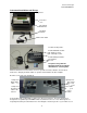
Veris Technologies Pub. #OM MSP03-1 Instrument Installation and Set-up The Veris Instrument Kit includes the following items: Protective case EC and pH Instrument Mounting Bracket Power Cable Trouble-shooting items: Included with EC module: EC signal test load EC continuity test box Included with pH module: pH simulator fuse kit Keep these along with the Operating Instructions with the unit whenever collecting data.
Veris Technologies Pub. #OM MSP03-1 magneto, consider powering the Veris instrument with a 12-volt battery or converting to an alternator system. The Veris MSP is shipped with an accessory power plug. If an alternative connection is desired, make sure that the unit is properly connected to a power connection that is not controlled by the ignition switch. If connecting directly to the battery, we suggest a 3 amp. in-line fuse is installed between the battery and the instrument.
Veris Technologies Pub. #OM MSP03-1 About the Veris EC output file format Veris EC data is output as a 5 column ASCII text file. Column A: longitude, B: latitude, C: EC Shallow Array (mS/m), D: EC Deep Array (mS/m), E: DGPS elevation (meters): Long. Lat. E.C. Shallow E.C. Deep Elevation -88.7579 43.49488 2.2 5.9 291.2 About the Veris pH output file formats 3 files are created during pH data acquisition: one containing the raw millivolt readings of the electrodes in soil (VPHL000.
Veris Technologies Pub. #OM MSP03-1 This is the second window you will see after powering up the unit. Select 3 to download or delete files that are stored on the Instrument or the removable CF card. Select option 1 to copy all data files stored in the Instrument’s memory to the removable CF card. The instrument will proceed to copy every data file stored on the instrument to the CF card. Select option 2 to delete ALL data files from the Instrument’s memory.
Veris Technologies Pub. #OM MSP03-1 d) The program will then ask you for a phone number. Instead of entering a phone number, specify the proper serial port number. For example, if Com 1 of the laptop is being used, specify “Direct to Com 1” under “connect using:” at the bottom of the entry area. e) HyperTerminal will then display a configuration menu where you can specify 4800 bits per second, 8 data bits, no parity, 1 stop bit and no flow control.
Veris Technologies Pub. #OM MSP03-1 Running Utility Files Utility files can be run from the CompactFlash card to perform various tasks. Here are the general instructions for running utility files: 1. 2. 3. 4. 5. Shut Instrument off and remove CompactFlash card. Always turn the instrument off before removing the CF card. Insert CompactFlash card into CompactFlash card USB reader. Plug USB reader into computer. Copy the file VERIS.BAT from your computer to the CompactFlash card.
Veris Technologies Pub. #OM MSP03-1 Soil EC Surveyor Installation and Set-up If the unit has been crated and delivered via closed-van commercial freight, the tongue (if equipped) may need to be installed prior to use. before doing so, please take precautions to ensure that the framework is properly supported to ensure safety. Remove bands that attach tongue assembly to shipping pallet.
Veris Technologies Pub. #OM MSP03-1 Closed center hydraulic kit poppet valve Fill gasoline engine and check engine and hydraulic oil levels. Before filling tank with gasoline, let engine cool. Gas vapors can ignite and an explosion can occur. Checking the hydraulic fluid level is easy thanks to a sight glass on the hydraulic reservoir. The sight glass is located on the front of the reservoir. Maintain the hydraulic fluid within 1/2 inch (1.25 cm) of the upper (solid black) line on the glass.
Veris Technologies Pub. #OM MSP03-1 • Escaping fluid under pressure can penetrate the skin causing serious injury. Avoid the hazard by relieving pressure before disconnecting hydraulic lines. Use a piece of paper or card-board, NOT BODY PARTS, to check for suspected leaks. • Wear protective gloves and safety glasses or goggles when working with hydraulic and highpressure wash systems. • If an accident occurs, see a doctor immediately.
Veris Technologies Pub. #OM MSP03-1 Signal Cable Attach the signal cable to the quick connect coupler at front of frame, and to Signal Port on back of instrument Adjustable Wing Extensions (XA option) The MSP3150 with XA (Extendable Array): This option allows the re-positioning of the electrodes to fit various bed and crop configurations.
Veris Technologies Pub. #OM MSP03-1 Turn on Veris instrument. The first screen to appear contains the software version number and shows how much logging time is available. The computer is informing you of how much of its internal memory is available. Check available memory to be sure you have enough to contain the data from field you are about to map. Options: Press any key and proceed to menu options.
Veris Technologies Pub. #OM MSP03-1 SEE GENERAL INFORMATION SECTION FILE MANAGEMENT FOR INSTRUCTIONS ON DOWNLOADING DATA Maintenance and Lubrication Proper maintenance and lubrication of the Veris MSP will allow you to collect high quality EC data and greatly extend the useful life of the unit.
Veris Technologies Pub. #OM MSP03-1 Connect one lead to Test Box terminal (corresponding to each coulter) Ohmmeter Connect to coulter blade c) Continue to check each coulter electrode in succession, left to right. d) If any coulter electrode exhibits no continuity or resistance higher than 2 ohms, refer to the maintenance or trouble shooting sections for possible causes.
Veris Technologies Pub. #OM MSP03-1 the commutators should be checked. This may be performed in the following manner: 1) Remove the 3/8” allen head set screw. 2) Remove the commutator by turning counter-clockwise. 3) Depress the spring loaded tip on a hard surface to determine if plunger has adequate tension and can move freely. 4) If the plunger will not move freely, replace, and coat with di-electric silicone grease.
Veris Technologies Pub. #OM MSP03-1 an upper and lower grease zerk. Due to the limited motion of the rockshaft, these should be lubricated on 40-hour intervals. This may vary based on the number of times the unit is raised and lowered.
Veris Technologies Pub. #OM MSP03-1 grease zerk Wheel hubs -On an annual basis, disassemble, clean, and properly repack the wheel hubs with suitable wheel bearing grease. It is advisable to replace the seals. As with any tapered roller bearing, proper pre-load will extend the life of the assembly. Fully tighten the nut, then rotate backward up to ¼ turn, so that the hub turns freely, without endplay. Install cotter pin, and reinstall hub cap.
Veris Technologies Pub.
Veris Technologies Pub. #OM MSP03-1 EC MODULE TROUBLESHOOTING Map doesn’t match known or expected soil types -1. Check electrical continuity using Implement Test Box as discussed above. 2. Check isolation of coulter electrodes 3. Remove any buildup of moist soil on toolbar 4. Check blade bolt tightness and corrosion 5. Map additional fields to see if similar condition results 6.
Veris Technologies Pub. #OM MSP03-1 pH Manager Installation and Set-up If the unit has been crated and delivered via closed-van commercial freight, the tongue (if equipped) may need to be installed prior to use. Before doing so, please take precautions to ensure that the framework is properly supported to ensure safety. Remove bands that attach tongue assembly to shipping pallet.
Veris Technologies Pub. #OM MSP03-1 Before filling tank with gasoline, let engine cool. Gas vapors can ignite and an explosion can occur. Fill gasoline engine and check engine and hydraulic oil levels. Checking the hydraulic fluid level is easy thanks to a sight glass on the hydraulic reservoir. The sight glass is located on the front of the reservoir. Maintain the hydraulic fluid within 1/2 (1.25 cm) inch of the upper (solid black) line on the glass.
Veris Technologies Pub. #OM MSP03-1 ball valve: closed open Connecting cables to External controller as shown below: Remove pH electrodes from individual storage containers and fill soaker solution container with soaker solution. Install soaker solution container on electrode holder. Loosen plastic set screws on electrode holder and insert pH electrodes into electrode holder. Re-tighten set screws finger tight and lock in place with lock nuts. Do not overtighten set screws or electrode damage may occur.
Veris Technologies Pub. #OM MSP03-1 Field Operations Tools required for Field Operation adjustments -3/16” allen wrench -adjustable wrench: min. 10” (25 cm) length -3/4” socket and wrench -9/16” socket or wrench -15/16” wrench Starting Engine Turn fuel valve to On position by sliding it to the far right. Move the choke lever to the far left Closed position, if engine is cold. Slide the throttle lever slightly to the left. Turn the engine switch to the on position. Turn key on.
Veris Technologies Pub. #OM MSP03-1 2. Put external controller in Manual mode and raise and lower sampler assembly. Keep appendages clear of pinch points. 3. Turn wash system on. If water does not flow from jets within 10 seconds, disconnect quick couplers to help pumps prime. If water doesn’t flow from pump outlet after 10 seconds, see Trouble-shooting section.
Veris Technologies Pub. #OM MSP03-1 operate implement parallel to soil 2. Once unit is level, lower sampling mechanism completely, drive forward 10-20’ (3-6 m) to create soil core. To measure depth of soil core being collected, brush away soil from cutting shoe. Measure from soil surface to top of cutting shoe. This is the depth of sampling. To increase sampling depth, remove cylinder stops; to decrease sampling depth, add stops. Re-leveling unit with adjustable toplink may be required.
Veris Technologies Pub. #OM MSP03-1 Other Field Adjustments Once EC coulter depth and sampling depth are satisfactory, adjust other components in this sequence: 1. Scraper adjustment: in manual mode hydraulically raise the sampling shoe to maximum height. Adjust scraper until cutting shoe clears scraper blade when sampler shank is fully raised. Adjust scraper bracket until cutting shoe clears scraper when sampler assembly is raised completely. 2.
Veris Technologies Pub. #OM MSP03-1 When installing BNC cover, route electrode wires under box; center box on white pad, and tighten wingnut finger tight. Keep cover installed even when electrodes are removed. When wash jets are properly aligned, overspray is minimized and water bubbles out top of electrode holder as shown here. 4. Insert pH electrodes into electrode holder. Finger-tighten plastic screws. Install BNC cover on external controller to keep moisture out of BNC connectors.
Veris Technologies Pub. #OM MSP03-1 7. Prox sensor: The prox sensor communicates the position of the sampler assembly to the external controller for automatic cycling functions. Adjust sensor to 1/4”- 3/8” (6-9 mm) gap. Cycle unit manually to insure that this gap is maintained throughout cycling range. Red LED light should light whenever prox sensor is near metal and not light when away from metal. To view LED light, shade ambient light from prox sensor and cycle sampler assembly manually.
Veris Technologies Pub. #OM MSP03-1 7. You will be asked for the ID of the electrode connected to channel 1. Use the 1 and 2 keys to change the number and 3 to confirm: Repeat for electrode 2’s ID and press 3 to confirm. 8. The instrument will prompt for the electrodes to be inserted into pH buffer 4 solution; Slide pH 4 buffer solution container onto electrode holder. Press 1 to continue with calibration or 2 to exit. 9.
Veris Technologies Pub. #OM MSP03-1 19. If the readings are satisfactory, log pH 7 reading and press 1; if the readings are suspect, press 2 to return to step 16. After accepting the pH 7 buffer readings, the Instrument will determine if each electrode’s response is sufficient to provide suitable readings. A score is displayed for each electrode; the acceptable score range is between 75 and 102. If both electrodes are within this range, the instrument will display the following screen: 20.
Veris Technologies Pub. #OM MSP03-1 Collecting pH data Set external controller to Automatic mode. Turn on Veris instrument. The first screen to appear contains the software version number and shows how much memory is available. Check available memory to be sure you have enough available to contain the data from field you are about to map. Options: Press any key and proceed to menu options. Press 1 and begin acquiring data (see below for more details). Press 2 and enter Setup menu.
Veris Technologies Pub. #OM MSP03-1 Maximum log time is the longest time in seconds the pH controller will wait for the pH readings to settle. The controller usually cycles before this maximum time is reached. The minimum setting for the maximum log time is 20 seconds. Press 1 or 2 to adjust the sample time, press 3 to continue to the next screen. Select the type of water you are using to clean the electrodes between samples. The available types are TAP, RO (reverse osmosis), or DI (de-ionized).
Veris Technologies Pub. #OM MSP03-1 pH and EC (option 3): DGPS indicator: NONE, _GPS, DGPS Speed in MPH Shallow and Deep EC readings pH readings from each electrode if equipped with pH module Status of pH sampling mechanism The display is showing the pH values from the pH electrodes, conductivity of the top 1’ (30 cm) and top 3’ (90 cm) of the soil, and whether you have GPS or DGPS (differentially corrected) signal. At any time during the mapping process, you can press the 4 key to stop the file.
Veris Technologies Pub. #OM MSP03-1 See the troubleshooting section if this occurs frequently. The Veris MSP pH Manager uses two electrodes for optimal data quality. If there is a difference of 0.75 or greater between the final electrode readings, an audible alarm will beep, informing the operator of the erroneous reading. To pause the data collection process at any time (but keep the same file), press the 1 key.
Veris Technologies Pub. #OM MSP03-1 Maximum log time is the longest time in seconds the pH controller will wait for the pH readings to settle. The controller usually cycles before this maximum time is reached. The minimum setting for the maximum log time is 20 seconds. Press 1 or 2 to adjust the sample time, press 3 to continue to the next screen. Select the type of water you are using to clean the electrodes between samples. The available types are TAP, RO (reverse osmosis), or DI (de-ionized).
Veris Technologies Pub. #OM MSP03-1 Exiting Data Acquisition and Extracting pH Data When you are ready to stop collecting pH data to the file, press 1. Wait for the unit to finish its current cycle and for the PRESS 1 TO START message in the controller message area before pressing 4 to exit data acquisition.
Veris Technologies Pub. #OM MSP03-1 the final settled smoothed soil pH readings (VPHE000.DAT). A formatting example of each file type follows: Raw millivolts (VPHLXXX.DAT): Long. Lat. Electrode 1 (mV) Electrode 2 (mV) Elevation Speed -88.7579 43.49488 -20 -25 291.2 4.5 Wash sequence millivolts (VPHWXXX.DAT): Long. Lat. Electrode 1 (mV) Electrode 2 (mV) Controller state -88.7579 43.49488 -20 -25 33 Extracted soil pH (VPHEXXX.DAT): LONGITUDE LATITUDE pH TIME ALTITUDE SPEED Sample Flag -88.7579 43.49488 6.
Veris Technologies Pub. #OM MSP03-1 Maintenance and Lubrication • Pinch point hazard: to prevent injury, stand clear when raising or lowering any part of the Veris MSP. Disengage automatic cycling function before working around unit. Install all transport locks before transporting or working underneath. Lubrication Rockshaft pivot points – Each pivot (located at the left and right) contains an upper and lower grease zerk.
Veris Technologies Pub. #OM MSP03-1 Leave BNC cover on whenever unit is outdoors. Wash System If wash water develops algae, flush and fill tanks with tap water; clean any algae or other foreign matter out of tank using clean-out ball valve (right side). Set wash system ball valve (left side) to open position, allowing water to flow to pumps. Clean filter at least once per week of operation. Remove plug and turn on ball valve to clean.
Veris Technologies Pub. #OM MSP03-1 knock worn shoe off from rear tap new shoe on with 2x4 Replace sampling trough liner, scraper cutting edge when wear is apparent. Hydraulic power pack Refer to provided Honda manual for complete information on Honda engine. engine oil dipstick Before filling tank with gasoline, let engine cool. Gas vapors can ignite and an explosion can occur. SERVICE REQUIRED Hydraulic Fluid Hydraulic Fluid Filter INTERVAL Check level at site glass on hydraulic fluid reservoir.
Veris Technologies Pub. #OM MSP03-1 Engine Sediment Cup Clean as Instructed in Honda Engines Manual. Engine Spark Plug Clean-Readjust as Instructed in Honda Manual. Replace as Instructed in Honda Engines Manual. NOTE: IN DUSTY FIELD CONDITIONS CHECK AND CLEAN AIR FILTER DAILY hydraulic oil filler plug hydraulic oil filter canister hydraulic oil sight glass hydraulic oil reservoir hydraulic oil drain plug • Escaping fluid under pressure can penetrate the skin causing serious injury.
Veris Technologies Pub. #OM MSP03-1 Change the filter cartridge whenever the hydraulic fluid is drained. Parker replacement cartridges (Veris P/N: RP9253) are available from Veris Technologies. One of the largest causes of service problems in the hydraulic functions is contamination. Whenever the hydraulic ends are inserted into the remote outlets, clean both the hydraulic end and the outlet. Keep covers on outlets when not in use.
Veris Technologies Pub. #OM MSP03-1 pH Module Troubleshooting 1. Unit doesn’t cycle when “1” key is pressed (in Automatic Mode) -check to be sure you are in Data Acquisition mode—screen below: -check to be sure that external controller is in Automatic mode. If it isn’t, this screen will appear: -follow troubleshooting flow chart below and see related procedures at end of Troubleshooting Section.
Veris Technologies Pub. #OM MSP03-1 2. Functions Aren’t Working in Manual Mode -follow troubleshooting flow chart below and see related procedures at end of Troubleshooting Section. 3. Sampling mechanism locks up or mis-cycles -press “1” to disengage, turn external controller to Manual and check prox sensor adjustment (see Procedure #4 at end of Troubleshooting Section) -check DGPS signal -if status of sampler shows “Cycling” for long periods, set sampler shank to shallower position.
Veris Technologies Pub. #OM MSP03-1 Use pH simulator to test external controller and Veris instrument. On/Off key (Turn pH simulator OFF when test is completed) Attach to each BNC port to test each circuit Press Select button to toggle from 4 to 7 to 10. Light above pH value will light. View Veris instrument to confirm these readings at each simulator setting.
Veris Technologies Pub. #OM MSP03-1 11.
Veris Technologies Pub. #OM MSP03-1 Procedure #1: Checking power inside External Controller The Veris pH module requires a minimum of 12 volts at all times. 12 volts at the battery terminals is NOT sufficient power for the system to function, due to the significant current draw when the pumps and solenoids are engaged. Reduced voltage can be caused by corroded or dirty terminals, and an inadequately charged battery or failure in the charging system.
Veris Technologies Pub. #OM MSP03-1 POWER (12V) FUSE 1 (10A) and its LED FUSE 2 (250 mA) and its LED Figure 2. External Controller circuit board (metal cover removed) 2. Turn off power to External Controller, remove clear lid and remove and replace any fuse that has failed. 3. Check voltage with a digital voltmeter at power supply connection All functions must be engaged during this test.
Veris Technologies Pub. #OM MSP03-1 If voltage at power connector drops below 12 volts during this test: a) clean battery terminals b) check disconnect contacts c) hook power leads directly to battery—not through tractor power port d) charge battery 4. Check voltage at power cable (Figure 4). If 12V at cable but not on circuit board—call Veris Service Dept.
Veris Technologies Pub. #OM MSP03-1 Figure 1. Flowchart for trouble-shooting sampler hydraulics. 1. If cylinder doesn’t move at all in manual mode, check hydraulic flow. Does main lift cylinder function? If not, check ball valve on Power Pack (Figure 2), or tractor hydraulic lever position. If necessary, check flow with pressure gauge. Figure 2: Ball valve must be open for hydraulic flow 2. Inspect LED’s on External Controller circuit board.
Veris Technologies Pub. #OM MSP03-1 SOLENOID LED’s UP DOWN Figure 3. External Controller circuit board (metal cover removed) 3. Test voltage coming out of External Controller to solenoids. Disconnect the weather-pack connectors in line from Controller to the solenoids. Using a digital voltmeter set to read voltage, insert leads into connector coming from Controller. Activate manual raise-lower switch and read voltage. (Figure 4) Voltage should be 12 volts. Figure 4.
Veris Technologies Pub. #OM MSP03-1 Figure 5. Testing continuity of solenoid coil (at weather-pack connector on jumper-wire) 5. Determine if coil is energizing. (This test integrates the previous two steps—if you have 12 volts going to the coil and the coil is functioning (has continuity), the coil should energize.) Touch a small screwdriver or other metal object to the coil as shown in Figure 6, and activate manual raise/lower switch. When the coil energizes it will hold the metal magnetically.
Veris Technologies Pub. #OM MSP03-1 Procedure #3: Trouble-shooting Communication Problem between Instrument and External Controller Communication between the Veris Instrument and the External Controller is required for the system to initialize (sampler cylinder moves to neutral), and function. A communication failure between these components may be expressed as INIT ERR (initialization error) or COMM ERR (communication error). Follow flow chart below to address problems in their logical sequence. Figure 1.
Veris Technologies Pub. #OM MSP03-1 Figure 2. Inspecting pins on communication cable 2. Testing continuity on communication cable. a) Unplug the communication cable from the Instrument. b) Bring both ends of the communication cable close enough together to reach with a voltmeter. c) Set your voltmeter to resistance (or continuity). Check continuity between the following pins: (Figure 3.
Veris Technologies Pub. #OM MSP03-1 d) Check continuity from brown Molex connector to 9 pin serial connector; this tests continuity from the circuit board to the instrument. (Figure 5) Molex Connector 4-pin connector 9 pin serial connector White 2 3 Green 1 2 Black 3 5 Figure 5. Testing continuity from Molex connector to serial connector 4. Testing that the external controller is receiving/acknowledging the command sent to it by the Instrument. a) Turn on the external pH Controller.
Veris Technologies Pub. #OM MSP03-1 5. Testing that the instrument is sending the proper command to the external controller. a) Connect the Instrument to the PC using a serial cable (you will need a null modem and may need a gender changer). Turn on the Instrument and enter data acquisition. The data in Hyper Terminal should look like this $U♥♦Ç$U♥♦Ç The important letter above is the ‘U’, but the data coming up should match this character-for-character.
Veris Technologies Pub. #OM MSP03-1 Procedure #4: Trouble-shooting Prox Sensor The prox sensor, located on the left of the sampler shoe parallel linkage arm, is critical to the machine’s function. It informs the external controller of the sampler’s position, which allows the controller to move the sampler to the next position in the sampling/measuring sequence. If the prox sensor is not functioning properly, the entire operation will be affected.
Veris Technologies Pub. #OM MSP03-1 1/4 to 3/8” gap (6-9 mm) Figure 2. Prox sensor gap 3. Adjust prox sensor height if needed. Loosen bolt holding prox sensor arm and rotate to change height of prox sensor (Figure 3). Adjust prox sensor height with sampler shoe completely raised. Adjust the prox sensor so it barely clears the lower part of the sensor plate when sampler is completely raised. It may be necessary to reposition the electrode holder and/or sampler shoe after adjusting prox sensor.
Veris Technologies Pub. #OM MSP03-1 Procedure # 5 Compact Flash card formatting Insert a Compact Flash card into a CF card reader which connected to your computer. Open “My Computer” folder. Right click on the CF card icon, and select the “Format”. In the format window, click on the file system tab and select “FAT” not “FAT32”. Then press “Start”. When complete, remove the card.