
Install Instructions

Installation Guide
Current Monitoring
Z207062-0A Page 1 of 3 ©2015 Veris Industries USA 800.354.8556 or +1.503.598.4564 / support@veris.com 0115
Alta Labs, Enercept, Enspector, Hawkeye, Trustat, Aerospond, Veris, and the Veris ‘V’ logo are trademarks or registered trademarks of Veris Industries, L.L.C. in the USA and/or other countries.
Other companies’ trademarks are hereby acknowledged to belong to their respective owners.
TM
HAZARD OF ELECTRIC SHOCK, EXPLOSION, OR ARC FLASH
• Follow safe electrical work practices.
See NFPA 70E in the USA, or applicable local codes.
• This equipment must only be installed and serviced by qualified electrical personnel.
• Read, understand and follow the instructions before installing this product.
• Turn off all power supplying equipment before working on or inside the equipment.
• Product may use multiple voltage/power sources. Disconnect ALL sources before
servicing.
• Use a properly rated voltage sensing device to confirm that power is off.
DO NOT DEPEND ON THIS PRODUCT FOR VOLTAGE INDICATION.
• Current transformer secondaries must be shorted or connected to a burden at all times.
• Products rated only for basic insulation must be installed on insulated conductors.
• Replace all doors, covers and protective devices before powering the equipment.
Failure to follow these instructions will result in death or serious injury.
A qualied person is one who has skills and knowledge related to the construction and
operation of this electrical equipment and installations, and has received safety
training to recognize and avoid the hazards involved. NEC Article 100
No responsibility is assumed by Veris Industries for any consequences arising out of the
use of this material.
DANGER
NOTICE
• This product is not intended for life or safety applications.
• Do not install this product in hazardous or classied locations.
• The installer is responsible for conformance to all applicable codes.
• Mount this product inside a suitable re and electrical enclosure.
Product Overview
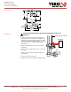
The H6ECM is a current-sensitive switching device that monitors current (amperage) in the conductor passing
through it. A change in amperage in the monitored conductor that crosses the switch threshold causes the
resistance of the FET status output to change state, similar to the action of a mechanical switch. The status output
is suitable for connection to building controllers or other appropriate data acquisition equipment operating at up to
30 volts. The product requires no external power supply to generate its output.
Electrically Commutated Motors (ECMs) are increasingly common as more energy conservation measures are
implemented. The ECM is a brushless DC motor that is supplied AC power, converts that power to DC current and
uses electronic switching to control the motor rotation. The ECM shaft speed can be reduced to save energy,
resulting in lower cost and less component wear. The H6ECM is optimized to provide meaningful proof of rotation
which verifies that the ECM motor is operating as expected.
Product Identification
ECMSeries: HECM
Split-Core Current Switch,
Proof of Rotation (Flow) for ECM Systems
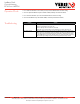
Specifications
Sensor Power Induced from the monitored conductor
Amperage Range 0.5 to 175A continuous
Status Output Ratings N.O. 1.0A @ 30VAC/DC, not polarity sensitive
Insulation Class 600VAC RMS (UL)
Threshold 0.5A
Frequency Range 60Hz only
Accuracy
±10%
Temperature Range -15° to 60°C (5° to 140°F)
Humidity Range 10-90% RH non-condensing
Hysteresis 10% typical
Off State Resistance Open switch represents > 1MΩ
On State Resistance Closed switch represents < 200mΩ
Terminal Block Max. Wire Size 24 to 14AWG (0.2 to 2.1mm
2
)
Terminal Block Torque 3.5 to 4.4 in-lbs (0.4 to 0.5N-m)
COMPLIANCE INFORMATION
Agency Approvals UL508 open device listing
Installation Category Cat. III, pollution degree 2
For applications requiring double or reinforced insulation, please contact the factory.
The product design provides basic insulation only.
Do not use the LED indicators as evidence of applied voltage.
TM
RoHS
Compliant
H6ECM 05
Sensor Type
05 = 0.5A threshold (tenths of amps)