Verizon 5G Extender TR1V1 User Guide Version 1
Federal Communication Commission Interference Statement This device complies with Part 15 of the FCC Rules. Operation is subject to the following two conditions: (1) This device may not cause harmful interference, and (2) this device must accept any interference received, including interference that may cause undesired operation. This equipment has been tested and found to comply with the limits for a Class B digital device, pursuant to Part 15 of the FCC Rules.
RF Exposure Statement To comply with FCC RF exposure compliance requirements, the antenna used for this transmitter must be installed to provide a separation distance of at least 32 cm from all persons and must not be co-located or operating in conjunction with any other antenna or transmitter.
Table of Contents Chapter 1 Introduction ..................................................................................................................................... 1 1.1 Unboxing Information........................................................................................................................... 1 1.2 Front Panel ............................................................................................................................................ 2 1.3 Back Panel ...........
Chapter 1 Introduction This chapter includes a list of items included with the TR1V1 5G Extender and a description of the user interface and ports on the device. 1.
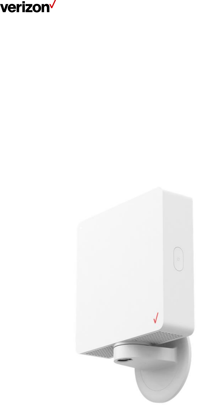
1.2 Front Panel An LED indicator is located in the top-left corner of the Extender’s front panel. LED Light Guide Device Status Description LED Status Booting up The Extender is powered and in the process of booting up. Solid: White Ready to pair The Extender is ready to be paired with the 5G nodes. Blinking: Blue Ready to scan The Extender is connected to the 5G nodes. Solid: Blue Scanning The Extender is scanning the signal strength from the 5G nodes.
Paired: No/Bad Signal There is no signal from the 5G nodes. Solid: Red Regular usage The Extender is working normally. Off An error has occurred (ex. pairing/FW issue) Blinking: Red The Extender is ready to reboot after a FW update. Fast Blink: White (Occurs during the 2 seconds prior to reboot/power off) Error FW Update / Reset 1.3 Back Panel 1. Product label and QR code Scan the QR code on this label with the Installer app to enable the receiver to establish a connection with the Extender.
1.4 Bottom Panel 1. DC jack Plug the AC adapter into this jack to power the Extender. 2. Screw holes The securing screw for the mounting bracket should be fastened into one of these holes. 1.
1. Scan button Use this button to scan for 5G signals from 5G nodes located outdoors. You may also press and hold this button for 3 seconds to switch between regular mode and installation mode. In addition, pressing and holding this button for more than 20 seconds triggers the factory reset process. 2. Raised nubs The raised nubs on the mounting head fit into the dimple holes on the inside of the mounting bracket’s installation slot. 1.
1. Mounting holes Wall screws are screwed through these mounting holes during wall installation. 2. Bracket cover This cover is attached to the top of the bracket’s base. Remove the cover before attaching the mounting bracket to a wall. 3. Installation slot Install the mounting head of the Extender into this slot. Once installed in this slot, the Extender can be rotated to either the left or to the right if the central position is not adequate for performance purposes. 4.
Chapter 2 Mounting the 5G Extender This section describes how to mount the 5G Extender onto window glass or walls. 2.1 Window Mounting 1. Use the provided alcohol swab to clean the area around the label, and wait for the alcohol to dry. 2. Peel off the protective backing on the Gecko Tape on the base of the mounting bracket, then affix the bracket onto the labeled area on the window. Follow the instructions printed on the protective backing of the Gecko Tape to ensure the bracket is securely affixed.
3. Once the bracket is securely affixed to the window, align the mounting head on the Extender with the installation slot on the bracket, then push down on the Extender to insert the mounting head into the slot. Adjust the alignment of the Extender as required (make sure the raised nubs on the mounting head fit into the dimple holes on the inside of the slot, and that the hole for the DC jack is aligned with the hole for the AC adapter on the bottom of the slot). 4.
2.2 Wall Mounting Note: The Extender can only be mounted on drywall or wooden walls. 1. Find a location on the wall near where the installation location label is placed. Peel off the protective backing on the Gecko Tape on the back of the mounting bracket, and remove the cover on top of the bracket base. Afterwards, place the mounting bracket against the wall at the aforementioned location using the same alignment used for window installation. 2.
4. For installation on wooden walls, after completing the steps in item 2, use a power tool and slowly screw the included metal screws into the marked points until the bracket is securely fastened. Note: Do not install the mounting bracket onto slanted walls. 5. Once the bracket is securely fastened to the wall, align the mounting head on the Extender with the installation slot on the bracket, then push down on the Extender to insert the mounting head into the slot.
6. Once the desired alignment is achieved, use a screwdriver to screw the securing screw through the designated hole on the bottom of the installation slot and into one of the screw holes on the mounting head of the Extender. Make sure the screw is screwed in tightly and is not loose. 7. Use the provided cable clips to conduct cable management.
Chapter 3 Product Specifications Hardware Specification • Support Frequency Band: n261 (27.5–28.35 GHz) • Separated TX & RX antenna arrays • Antenna array - 32 elements at donor side - 2 antenna panels at relay side, each has 4 elements • Peak EIRP at P1dB - Donor 46 dBmi - Relay 28 dBmi • Micro-controller and Memory - SPI NOR Flash • BLE 4.2 • DC Jack for 12 V/4 A power adapter • One RGBW LED • Buzzer × 1 • Operating Temperature: 5°C to 40 °C • Dimension: 181.5 mm × 181.5 mm × 49 mm • Weight: 1.