User Guide
EN Introduction The analogue drum-synthesizer DRM1 MKIII is not just another instrument or piece of equipment. It is also part of history - our history. In its first version, we have reentered the market under the brand name Vermona with a first product. A return to a market from which we temporarily had to pull back due to significant historical and political changes. This product was introduced many years ago but the DRM1 is still being produced.
Table of Contents Introduction..........................................................................................................................1 Important Safety Information............................................................................................3 Setup.......................................................................................................................................5 Scope of delivery............................................................................
EN Important Safety Information 1. 2. 3. 4. 5. 6. 7. 8. 9. 10. 11. 12. 13. 14. 15. 16. 17. 18. Read these instructions. Keep these instructions. Always include these instructions when passing the product on to third parties. Heed all warnings. Follow all instructions. Do not use this apparatus near water. Only clean the product when it is not connected to the mains power supply. Clean only with a dry cloth. Do not block any ventilation openings.
Installation • • • • • • 4 Ensure that the room in which you use this product is wired in accordance with the local electrical code and checked by a qualified inspector. Only use this product indoors. Do not install the product in hot, humid, or excessively dusty locations, in direct sunlight or in locations where it is exposed to externally generated vibrations. Do not place burning objects (e.g. candles) on top of or near the product. If condensation has formed on the product, e.g.
EN Setup Scope of delivery To ensure top quality, we carefully inspected the DRM1 MKIII before packaging. Nevertheless, the module could have been damaged during transportation. Therefore, we ask you to take a serious look at the unit when unpacking. Do not hesitate to contact us, should there be anything unusual with the unit or its packaging.
1. The jacks OUT LEFT and OUT RIGHT 9 on the module‘s rear output all signals in stereo. Connect these jacks to two line-inputs of a mixing desk, a computer-audio-interface or to an amplifier using two 6.3 mm cables (TS). Alternatively or in parallel, you may connect a headphone 7 on the module‘s front panel. NOTE 2. All of the DRM1 MKIII sound channels offer individual outputs 5 , allowing them to be patched to the inputs of a mixing console or an audio-interface.
EN Control elements and connections Front Panel/User Interface 1 KICK TRIG DECAY PITCH BEND TIME WAVE NOISE ATTACK PAN VOLUME OUT DRUM 1 TRIG DECAY PITCH BEND ATTACK FM INT FM FREQ WAVE PAN VOLUME OUT DRUM 2 TRIG DECAY PITCH BEND ATTACK FM INT FM FREQ WAVE PAN VOLUME OUT MULTI TRIG DECAY PITCH BEND ATTACK PITCH 2 PITCH 3 HIGHPASS PAN VOLUME OUT SNARE TRIG DECAY R REVERB DECAY N NOISE ATTACK RESO FILTER PAN VOLUME OUT HI HAT 1 TRIG DECAY FILTER
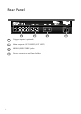
8 8 9 8 Trigger-inputs (optional) 9 Main outputs (OUT RIGHT/OUT LEFT) 10 MIDI-IN/MIDI THRU jacks 11 Power connector and fuse holder 10 11 Employer uniquiment avec un fusible de 250V Use only with a 250V fuse Rear Panel
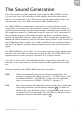
EN The Sound Generation Now that you have carefully unpacked and setup the DRM1 MKIII, let’s take a closer look. Sorry for bothering you with mainly theoretical and security aspects. To get the most out of this unit in a creative and musical sense, this was necessary. Now, let’s find out what the DRM1 MKIII really is! The DRM1 MKIII is a sound module, specialized to create synthetic drum sounds that are produced by pure analogue circuits.
VOLUME this control adjusts the channel’s volume for the main- 9 , headphone- 7 and individual outputs 5 . The DRM1 MKIII’s sound channels The eight sound channels are tailored to generate specific drum sounds. However, thanks to their flexibility, you are explicitly asked to experiment and get creative. You will find out that each channel offers plenty of different sounds.
EN With pitch modulation being completely absent, bass drums may sound flat and not distinctive; therefore we recommend at least a little dose of BEND. To create dance-kicks use higher BEND settings and lower TIME settings. For long booming kicks keep the control in the lower half. With PITCH being set to its maximum, BEND can no longer fully modulate the pitch. TIME adjusts the release time of the pitch envelope.
DRUM 1/DRUM 2 DRUM 1 TRIG DECAY PITCH BEND ATTACK FM INT FM FREQ WAVE PAN VOLUME OUT The two DRUM channels are built identically. These are meant to create toms, percussions and metallic sounds but can also produce bass drums differing in character to the KICK channel. Thanks to two available channels you may either create two completely different sounds or create sound pairs such as low and hi toms or congas. DECAY sets the release time or the sound’s length.
EN FM FREQ sets the modulation frequency. Here, the sound is modulated in pitch using a sine wave. With values starting from the knob’s 9 o’ clock position, the modulation enters the audible range, resulting in a broad frequency spectrum. This allows creating atonal and metallic timbres. At lower values, FM will result in modulations comparable to a typical LFO. WAVE is a mix control that seamlessly blends a sinusoid wave form into a rectangular shape. Here, the sound changes from soft to harder.
ATTACK adds a short fixed needle impulse to the sound’s start to support its assertiveness. Always adjust ATTACK in correlation to the complete mix. What might appear too intrusive when being soloed might already sound too gentle within a full mix. We recommend adding a little ATTACK even to soft drum sounds. PITCH 2 sets the pitch/frequency of the second oscillator. However, its base pitch is tied to PITCH. Changing PITCH will always change the frequency of PITCH 2, too.
EN SNARE SNARE TRIG DECAY R REVERB DECAY N NOISE ATTACK RESO FILTER PAN VOLUME OUT The duty of the SNARE channel is apparent. However, due to its various parameters, the DRM1 MKIII’s snare drum is a lot more changeable than you might guess from previous analogue drum machines. The sound is build up from different components: Noise, a needle impulse, a resonance filter and a pseudo reverb.
RESO specifies the intensity of the filter’s resonance and, as a result, colors the tonal component of the snare sound. Only at higher values, the filter will start to self-oscillate. This parameter interacts with ATTACK, whose needle impulse initiates the filter’s oscillation. FILTER sets the cutoff frequency of the low pass filter. Presuming the filter has been excited to oscillate, this control adjusts the pitch of the snare’s tonal sound component.
EN HI HAT 1/HI HAT 2 HI HAT 1 TRIG DECAY FILTER BEND ATTACK RESO MIX PITCH PAN VOLUME OUT These two channels are meant to create hi-hats but also cymbal sounds. Achieve a broad spectrum of cymbals, percussions and sound effects on a basis of filtered noise and a metallic oscillator mixture. DECAY sets the release time or the sound’s length. FILTER sets the cutoff frequency of the low pass filter, coloring the overall sound of the channel.
PITCH NOTE 18 defines the pitch/frequency of the oscillator mix as well as for the ATTACK impulse. Both HI HAT channels can be triggered in two versions, using the TRIG button - either as cymbal/open hi-hat or as closed hi-hat. The closed hi-hat has a fixed, short decay time, independent of the DECAY control. After switching on, the DRM1 MKIII’s TRIG button defaults to trigger the cymbal/open hi-hat, with the sound’s length being defined by DECAY.
EN CLAP CLAP TRIG DECAY R REVERB CLAP NOISE RESO FILTER HIGHPASS PAN VOLUME OUT The CLAP channel serves a defined task. It simulates the clapping of several hands. Like the SNARE channel, CLAP also offers an electronic pseudo-reverb which, here, is an integral part of the sound and supports its authenticity. The CLAP channel also incorporates a resonance filter component. DECAY REV sets the length of the reverb effect. This parameter’s effect is only audible with REVERB being enabled.
MIDI Functions The DRM1 MKIII receives MIDI notes including corresponding velocity data. This way, the sound can be played dynamically. Other MIDI data such as controller data are not processed. Setting the MIDI-channel and note numbers A small notice to avoid misunderstanding the term “channel”. So far, the different sounds of the DRM1 MKIII have been simply referred to as “channels” (calling them instruments or sounds might have been misleading in some cases).
EN Setting the MIDI-channel and note numbers for all DRM-channels 1. Press any two TRIG buttons while switching the unit on. Press and hold the buttons until both sounds are triggered. 2. The unit has now entered learn mode. 3. Now, send a sequence of eight note numbers to the unit, e.g. by pressing notes on a connected keyboard. All note numbers and the MIDI-channel used for transmission will be learned. The first transmitted note number refers to the first DRM-channel KICK.
4. After all DRM-channels have been assigned to note numbers, the unit automatically switches to play-mode. The note assignment is permanently stored until the next assignment is performed. NOTE While in learn-mode, the DRM1 MKIII restores its factory defaults when no note numbers are received before switching the unit off.
EN Individual Outputs/Inserts Each DRM-channel offers a dedicated individual output/insert with a choice of possible applications. Crucial to the outputs’ function is the cable being used, or to be more exact, the pin-assignment of the connector being placed in the output jack. Use as individual output The OUT jack can be used as an individual out in two ways. 1. By using a standard TS-cable, the signal will be automatically excluded from the main outputs: 2.
Use as insert The OUT jack can also be used to insert external effect processors into that channel, such as filters or delays. To do so, use a so-called Y-cable/insert-cable: • • • 24 Connect the TRS connector to the channel’s OUT. Connect the send connector to the input of the effect processor. Connect the return connector (often color-coded in red) to the output of the effect processor.
EN Trigger-Inputs (optional) You can purchase the DRM1 MKIII either with or without trigger-inputs. The eight trigger-inputs allow triggering the DRM1 MKIII’s sound from an analogue sequencer. The unit will accept gate signals between 2 and 12 volts. Alternatively, the mode of operation can be switched by internal jumpers to the use of switch-trigger. Note that this requires the unit to be opened which shall only be performed by a Vermona authorized service technician or expert.
Sound Examples The following illustrations are meant as initial points for different sounds. Explore the DRM1 MKIII’s sonic possibilities starting from here. These parameter settings are rough guidelines since analogue circuits always possess a life of their own. Especially when tuning the MUTLI oscillators or using frequency modulation, some millimeters may already make significant difference in sound.
A Game Drum DRUM 1 TRIG DECAY PITCH BEND ATTACK FM INT FM FREQ WAVE PAN VOLUME OUT DECAY PITCH BEND ATTACK PITCH 2 PITCH 3 HIGHPASS PAN VOLUME OUT DECAY PITCH BEND ATTACK PITCH 2 PITCH 3 HIGHPASS PAN VOLUME OUT DECAY PITCH BEND ATTACK PITCH 2 PITCH 3 HIGHPASS PAN VOLUME OUT PITCH BEND ATTACK PITCH 2 PITCH 3 HIGHPASS PAN VOLUME OUT MULTI Cowbell MULTI TRIG Lazer Zap MULTI TRIG Metallic Tic MULTI TRIG HP MiniChords MULTI TRIG DECAY DRM1 MKIII -
SNARE Compact Snare SNARE TRIG DECAY R REVERB DECAY N NOISE ATTACK RESO FILTER PAN VOLUME OUT REVERB DECAY N NOISE ATTACK RESO FILTER PAN VOLUME OUT Old Scool Snare SNARE TRIG DECAY R Tunable Drum SNARE TRIG DECAY R REVERB DECAY N NOISE ATTACK RESO FILTER PAN VOLUME OUT TRIG DECAY R REVERB DECAY N NOISE ATTACK RESO FILTER PAN VOLUME OUT DECAY FILTER BEND ATTACK RESO MIX PITCH PAN VOLUME OUT DECAY FILTER BEND ATTACK RESO MIX PITCH PAN VOLUME
A CLAP Full Claps CLAP TRIG DECAY R REVERB CLAP NOISE RESO FILTER HIGHPASS PAN VOLUME OUT DECAY R REVERB CLAP NOISE RESO FILTER HIGHPASS PAN VOLUME OUT DECAY R REVERB CLAP NOISE RESO FILTER HIGHPASS PAN VOLUME OUT Hollow Clap CLAP TRIG Short Guiro CLAP TRIG DRM1 MKIII - analog drum synthesizer 29
HDB electronic GmbH Badesteig 20 08265 Erlbach GERMANY Fon: +49 (0)37422 4027 0 Email: info@vermona.com Internet: www.vermona.