
- Vermont Castings Multi-Fuel Heater Homeowner's Installation and Operating Manual 2547CE


6
Encore Multi-Fuel Heater
2000971
sheet metal screws. The
pre-drilled holes in the top
of each section of chimney
connector serve as guides
when you drill 3 mm (1/8”)
holes in the bottom of the
next section.
• Secure the chimney
connector to the chimney.
Instructions for various in-
stallations follow.
• Be sure the installed
stove and chimney connec-
tor are correct distances
from nearby combustible materials.
NOTE: Special slip pipes and thimble sleeves that form
telescoping joints between sections of chimney con-
nector are available to simplify installations. They often
eliminate the need to cut individual connector sections.
Consult your local dealer about these special pieces.
Securing the Single-wall Connector to a
Prefabricated Chimney
Follow the installation instructions of the chimney
manufacturer exactly as you install the chimney. The
manufacturer of the chimney will supply the accesso-
ries to support the chimney, either from the roof of the
house, at the ceiling of the room where the stove is
installed, or from an exterior wall.
Special adapters are available from your local dealer
to make the connection between the prefabricated
chimney and the chimney connector. The top of such
adapters attaches directly to the chimney or to the
chimney’s ceiling support package, while the bottom of
the adapter is screwed to the chimney connector.
These adapters are designed so the top end will fit
outside the inner wall of the chimney, and the bottom
end will fit inside the first section of chimney connector.
When assembled in this way, any soot or creosote fall-
ing from the inner walls of the chimney will stay inside
the chimney connector.
Flue Pipes with a spigot and socket joint should be
fitted with the socket facing upwards, to contain con-
densates and moisture within the flue. Joints should be
made gas tight using proprietary jointing accessories,
or, where appropriate, by packing joint with noncombus-
tible rope and fire cement.
Double-wall connectors must be tested and listed for
use with solid-fuel burning appliances. Single-wall con-
nectors should be made of 24 gauge or heavier steel.
Do not use galvanized connector; it cannot withstand
the high temperatures that can be reached by smoke
and exhaust gases, and may release toxic fumes under
high heat. The connector may be 152 mm (6”) or 203
mm (8”) in diameter.
If possible, do not pass the chimney connector through
a combustible wall or ceiling. If passage through a com-
bustible wall is unavoidable, refer to the section on Wall
Pass-Throughs. Do not pass the connector through an
attic, a closet or similar concealed space. The whole
connector should be exposed and accessible for in-
spection and cleaning.
The recommended maximum length of a horizontal
stovepipe run is 152 mm (6”).
In cathedral ceiling installations, extend the prefabricat-
ed chimney downward to within 2.4 m (8’) of the stove.
Wear gloves and protective eyewear when drilling,
cutting or joining sections of chimney connector.
Double-wall Chimney Connectors
Information on assembling and installing double-wall
connectors is provided by the manufacturer of the
double-wall pipe. Follow the manufacturer’s instructions
exactly as you assemble the connector and attach it to
the stove and chimney. Using chimneys and connectors
from the same manufacturer makes the assembly and
installation straightforward.
NOTE: For installations using double-wall connectors,
minimum clearances must conform to the listed clear-
ances in the clearance chart on Page 13.
If the Encore Multi-Fuel is equipped with the 203 mm
(8”) flue collar, an oval-to-round adapter will be needed.
Your local dealer can help you select the right connec-
tor.
Single-wall Chimney Connectors
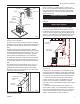
• Begin assembly at the flue collar of the stove. Insert
the first crimped end into the stove’s flue collar. Keep
each crimped end pointing toward the stove. (Fig. 5)
Using the holes in the flue collar as guides, drill 3 mm
(1/8”) holes in the bottom of the first section of chimney
connector and secure it to the flue collar with three #10
x 1/2” sheet metal screws.
• Secure each joint between sections of chimney con-
nector, including telescoping joints, with at least three
ST242
Chimney connector
12/13/99 djt
Fig. 4 the crimped end
of the connector points
toward stove.
Securing the Single-wall Connector to a
Masonry Chimney
Both freestanding masonry chimneys and fireplace ma-
sonry chimneys may be used for your installation.
Freestanding Installations
If the chimney connector must pass through a combus-
tible wall to reach the chimney, follow the recommenda-
tions in the Wall Pass-Through section that follows.
The opening through the chimney wall to the flue
(the “breech”) must be lined with either a ceramic or
metal cylinder, called the “thimble”, which is cemented